

Embedded Thermal Imaging Core Architecture
Integrating non-contact temperature detection and night vision into space-constrained enclosures frequently presents thermal management and signal routing headaches for electro-optical engineers. A dedicated thermal imaging core resolves these mechanical and electrical packaging bottlenecks by packaging the detector, drive electronics, and video processing pathways into a standalone subassembly. Rather than forcing integrators to engineer complex analog readout stages from scratch, modular sub-assemblies provide standard interconnects and mechanical mounting points that streamline development cycles for industrial machinery, mobile payloads, and security fixtures.
Product Overview and Visual Construction
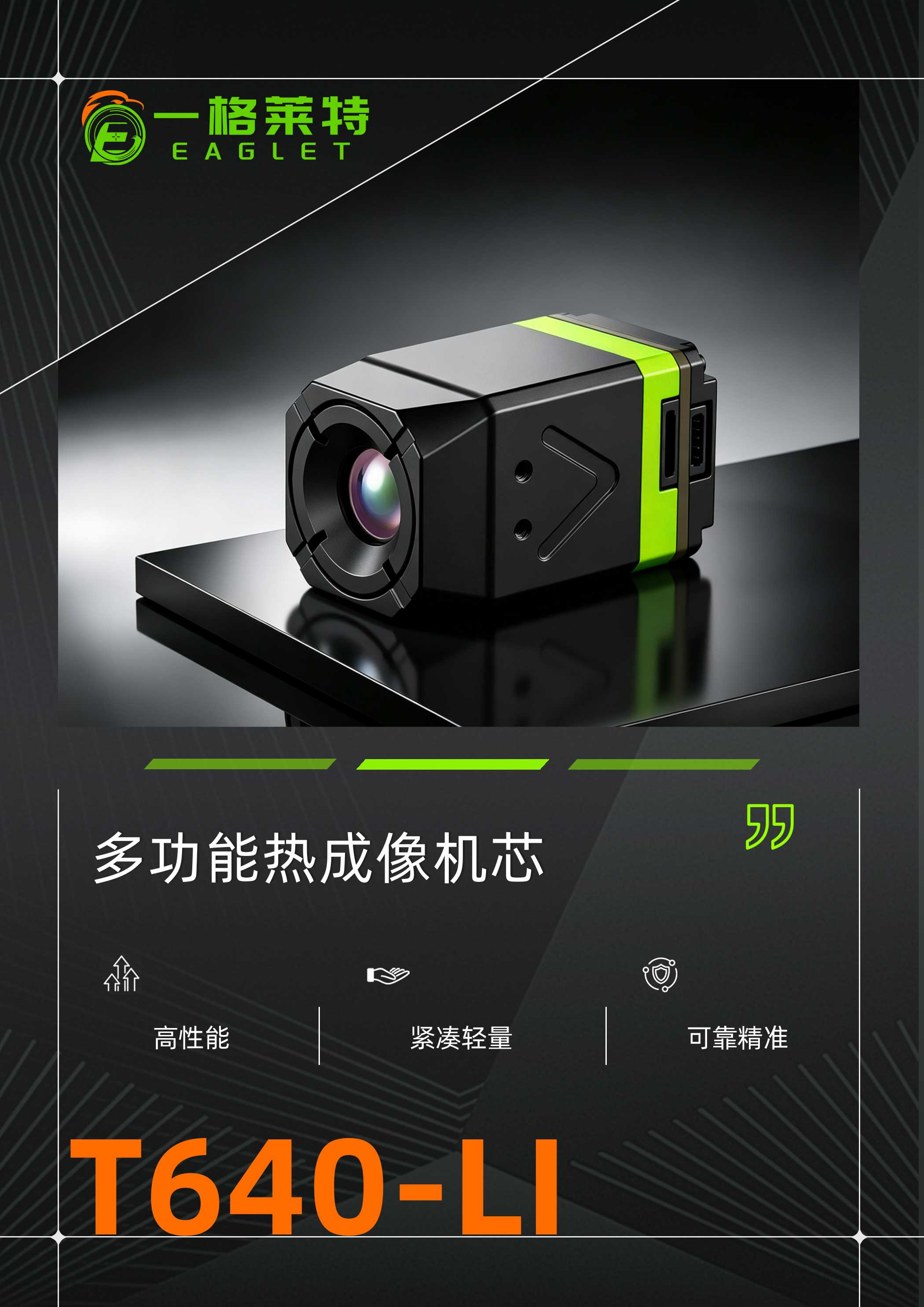
The unit features an enclosed rectangular profile engineered for embedded installation. Visually, the housing utilizes an angular, faceted exterior finished in matte black, accented by a distinct green perimeter identification band. The front face accommodates either an integrated optical assembly with anti-reflective lens coatings or a protective, screw-fastened ribbed cover designed for targeted thermal dissipation and mechanical shield protection. Recessed directional indicators and alignment features are molded directly into the lateral panels, accompanied by threaded mounting points to ensure repeatable indexing within host assemblies.
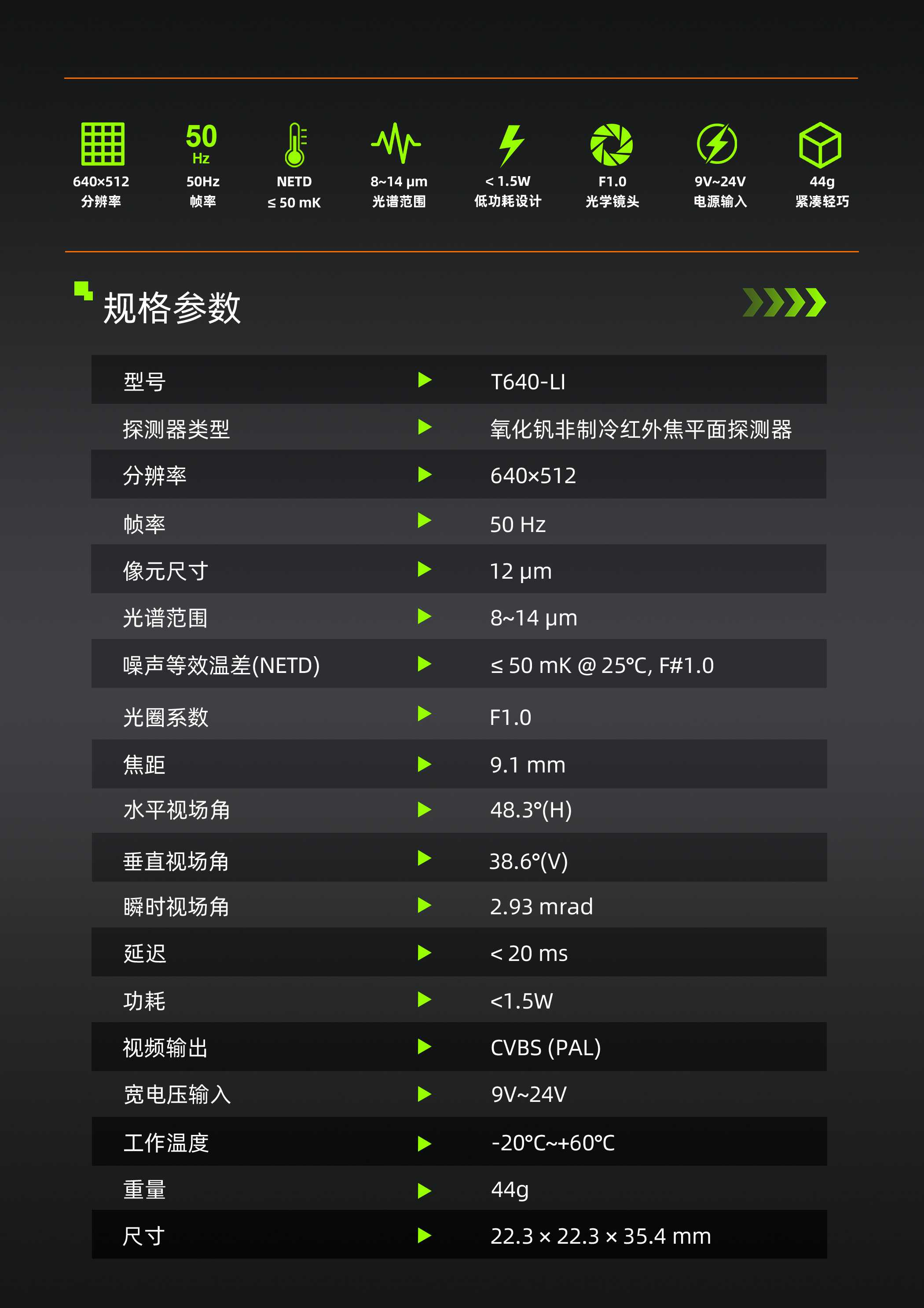
Electrical connectivity is grouped for clean cable harness management. Depending on the chassis version, interfacing includes direct front-panel solder pads or labeled terminal headers—visibly marked for CVBS analog video output, power, and ground—alongside dedicated multi-pin side and rear connectors. Models aligned with the Eaglet thermal core family and industrial designations like the T640-LI are built specifically to accommodate embedded integration where depth and volume limitations dictate connector placement.
Core Specifications and Operational Capabilities
Designed around modern solid-state sensor infrastructure, the thermal camera core utilizes an uncooled infrared core architecture. This solid-state design eliminates bulky mechanical cryocoolers, significantly reducing startup intervals and maintenance overhead. For applications demanding sensitive target differentiation across fluctuating ambient backgrounds, integrating an uncooled VOx thermal imaging core ensures uniform scene reproduction across the operational long-wave infrared band.
Key Integration Characteristics
- Signal Processing: Engineered for ultra low latency video output, enabling operators and autonomous navigation systems to make instantaneous adjustments during high-speed tracking or robotic guidance.
- Electrical Compatibility: Configured as a 9-24V supply thermal module, allowing wide-range direct DC input from industrial equipment buses, battery packs, or regulated airborne power distribution boards without requiring supplementary external step-down converters.
- Video Output Types: Standard CVBS analog signaling allows direct legacy monitor driving, while auxiliary high-density connectors facilitate system control, telemetry communication, and auxiliary digital interfacing.
Enclosure Materials and Manufacturing Process
The module chassis combines precision structural engineering with robust environmental resistance. The housing parts are fabricated via high-precision CNC machining or high-integrity alloy die casting, coated with a non-reflective matte finish to resist wear and suppress stray reflections. Front-facing ribbed elements provide mechanical stiffness while simultaneously serving as secondary conduction surfaces to manage internal heat rejection.
Electronics manufacturing relies on high-density surface mount technology (SMT) with rigid-flex interconnects to isolate the focal plane array from mechanical vibrations. Optical assemblies are aligned using multi-axis fixtures before final torque calibration on the retaining fasteners. While specific ingress protection ratings depend on final OEM enclosure sealing, the self-contained module design protects delicate sensor wire bonds and internal board layers from handling damage during downstream assembly.
Target Application Scenarios
The compact footprint and low power draw make this module versatile across multiple commercial and industrial sectors:
- Unmanned Systems and Airborne Payloads: Where ultra low latency feedback is mandatory for real-time pilot-in-the-loop navigation and gimbal-stabilized observation.
- Automated Industrial Inspection: Continuous process monitoring, electrical switchgear surveillance, and mechanical bearing inspection on active production lines.
- Security and Perimeter Protection: Embedded into stationary pan-tilt-zoom platforms or compact sentry cameras requiring analog composite video transmission over long coaxial runs.
- Robotic Guidance: Providing vision systems with reliable thermal contrast in low-light environments, dense smoke, or challenging visual conditions where standard RGB cameras fail.
Quality Control and Assembly Verification
Each imaging engine undergoes staged quality validation prior to shipment. Optical axes are verified against mechanical housing datums to guarantee proper line-of-sight alignment. Board-level testing confirms electrical stability across the entire input voltage range of the 9-24V supply thermal module framework. Units are subjected to burn-in thermal cycles to stabilize detector response, identify potential drift, and verify non-uniformity correction stability. Signal jitter and output stability are monitored to ensure strict adherence to ultra low latency video delivery thresholds under sustained operation.
Integration Guidance for System Designers
When incorporating an uncooled infrared core into an existing instrument shell, mechanical and thermal isolation must be balanced. Mount the core via its integrated side fastening holes using designated torque tolerances to avoid inducing mechanical stress on the optical barrel. Ensure adequate heat conduction away from the rear processing boards through chassis contact or localized airflow, especially when operating within sealed external enclosures. For system wiring, keep analog CVBS leads shielded and physically isolated from high-current motor drivers or switching power lines to preserve clean video quality.
Buyer Decision Factors and Inquiries
Selecting the right thermal imaging core requires evaluating available supply voltages, physical clearances, connector geometry, and display latency requirements. Whether configuring custom optics on the T640-LI or integrating the Eaglet thermal core within an autonomous vehicle vision package, matching interface protocols to host processing capabilities is critical to avoiding costly interface redesigns. Contact our technical integration team to discuss mechanical drawing requirements, interface pinouts, optical configurations, and prototype availability for your production schedule.