
Choosing an infrared thermal camera factory is an engineering and procurement decision, not simply a search for the lowest-priced infrared camera.
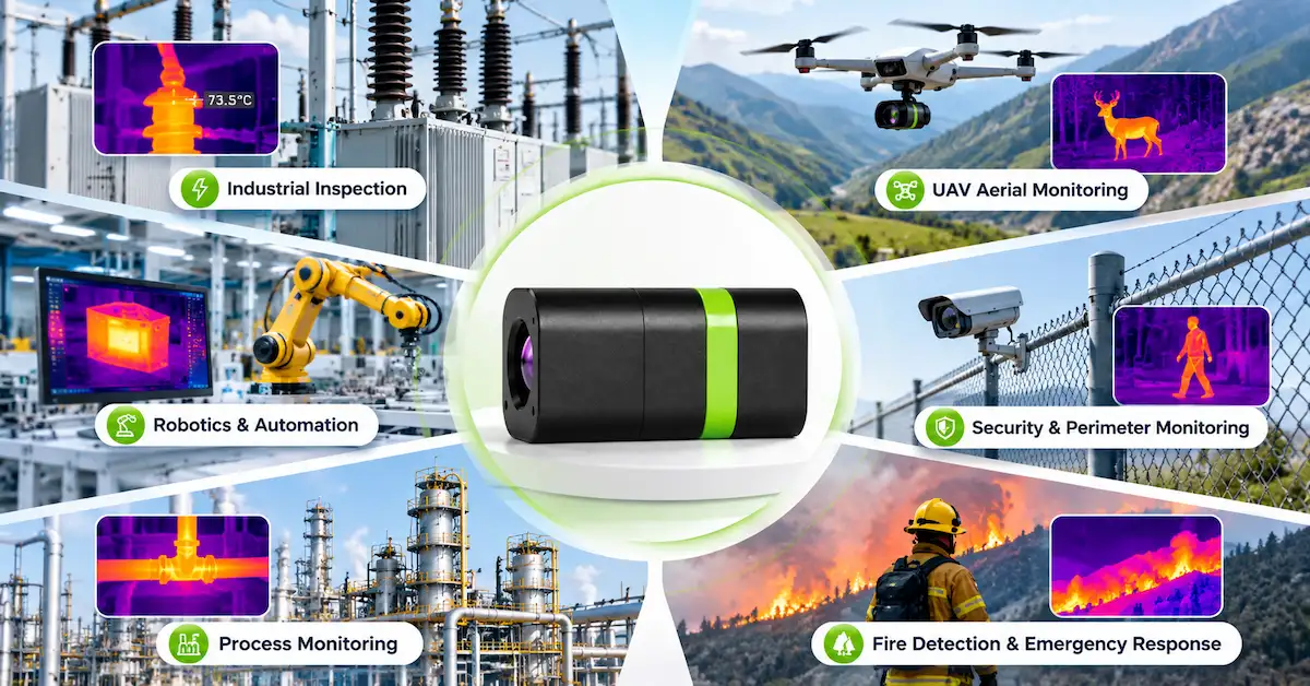
For an OEM equipment manufacturer, the thermal imaging component may become part of an industrial inspection instrument, an unmanned aerial vehicle, an autonomous robot, or a continuously operating monitoring system. Once integrated, a problem with the detector, lens, video interface, power supply, or production consistency can affect the entire product.
A supplier's sample might produce an attractive thermal image in a demonstration. That alone does not prove that the same configuration can be integrated successfully, manufactured consistently, or maintained across future orders.
The purchasing challenge is therefore broader: Can the factory provide the right thermal imaging architecture, explain its production responsibilities, support technical validation, and maintain a controlled product configuration?
This guide examines the factory-level evidence that matters, explains essential infrared specifications, compares published EAGLET thermal imaging cores, and provides a practical process for evaluating an OEM thermal imaging project before placing a production order.
1. What Should OEM Buyers Expect from an Infrared Thermal Camera Factory?
An infrared thermal camera factory should be evaluated according to its actual manufacturing scope, engineering responsibilities, product documentation, and ability to verify finished imaging performance. A supplier that develops thermal imaging cores may have different responsibilities from a company assembling complete handheld cameras or manufacturing infrared detectors.
An infrared camera system typically combines several technical elements:
| System element | Primary function | What OEM buyers should verify |
|---|---|---|
| Infrared detector | Converts incoming thermal radiation into an electrical response | Detector technology, resolution, spectral response, pixel pitch |
| Infrared optics | Focuses infrared energy onto the detector | Lens configuration, focal length, FOV, focus conditions |
| Imaging electronics | Processes detector signals into usable images | Image processing functions, frame rate, firmware, electrical requirements |
| Video and control interfaces | Connects the imaging module to external equipment | Output format, connectors, communication protocol |
| Mechanical integration | Positions and protects components | Dimensions, mounting, alignment, vibration and environmental requirements |
| Final equipment | Delivers the complete customer application | Display, software, housing, calibration, connectivity, regulatory requirements |
Not every factory manufactures all these elements internally.
An infrared imaging core supplier may purchase detector components, design processing electronics, integrate optics, assemble modules, and validate the resulting imaging system. Another manufacturer may specialize primarily in final camera assembly.
Neither business model is automatically superior. The appropriate choice depends on which parts of the development and manufacturing process the OEM customer intends to control.
For example, a company developing its own inspection robot may need a compact infrared module with clearly documented electrical and mechanical interfaces. It may not need a complete handheld camera with a display, battery, and operating system.
Conversely, a distributor seeking ready-to-sell professional inspection cameras may require a finished product, retail packaging, applicable documentation, and an established after-sales process.
Before requesting prices, buyers should define exactly what they are purchasing:
-
An infrared detector or sensing component
-
A thermal imaging core with optics and processing electronics
-
An imaging module requiring additional system integration
-
A complete customized thermal camera
-
A finished product ready for its intended market
This distinction prevents a common sourcing mistake: comparing quotations for products that contain very different levels of engineering and manufacturing work.
2. Which Buyers Benefit Most from a Factory-Level OEM Relationship?
Working with an infrared thermal camera factory can be valuable when the imaging hardware must fit a product architecture designed by the customer.
For an OEM project, technical collaboration may be as important as component availability. A finished camera that works well independently may be unsuitable when its dimensions, video interface, optics, or firmware cannot be adapted to the customer's platform.
Industrial inspection equipment manufacturers
Manufacturers of electrical inspection tools, machinery monitoring equipment, and automated inspection stations need thermal imaging hardware compatible with their intended observation distance, inspection target, and host electronics.
Their priorities often include stable imaging, repeatable product configuration, suitable optics, integration documentation, and reliable long-term availability.
Where quantitative temperature measurement is required, radiometric functionality, calibration procedures, and measurement accuracy become additional purchasing requirements.
UAV and drone payload manufacturers
Airborne equipment developers must consider the combined effect of module dimensions, weight, operating power, imaging latency, optics, and downstream video transmission.
A high-resolution detector may be attractive, but a physically unsuitable module can require a complete payload redesign.
Robotics and automation companies
Inspection robots frequently operate with limited installation space and predetermined electrical architectures.
An embedded thermal imaging module may need to connect to an existing video acquisition device, controller, or processing computer. The cost of changing those systems can exceed the price difference between two infrared cores.
Security and professional observation equipment developers
These buyers may prioritize field of view, nighttime thermal contrast, target visibility, mechanical installation, and environmental reliability.
Thermal imaging can support observation without visible illumination, but the required detection, recognition, or identification performance must be established for the intended target and conditions.
Importers and professional equipment brands
Some importers require consistent repeat orders, model identification, packaging, documentation, and commercial continuity rather than extensive custom engineering.
For these customers, factory qualification should include quality consistency, version control, product support, warranty terms, and the responsibilities of each contracting party.
Who may not need an OEM thermal core supplier? Buyers who require a complete consumer camera or an immediately deployable certified measuring instrument should first confirm that the supplier's offering includes those finished-product functions.
3. How to Audit an Infrared Thermal Camera Factory Before Ordering
A factory audit should establish what the supplier actually controls and what evidence supports its technical and manufacturing claims.
A modern production building, automated equipment photographs, or a detailed company brochure may be useful background information. They are not substitutes for a documented understanding of the product being purchased.
The following audit matrix can be used by OEM sourcing teams.
| Factory audit area | Evidence to request | Why it matters |
|---|---|---|
| Company and facility | Registered business information, factory location, relevant operating scope | Establishes the supplier's identity and manufacturing role |
| Engineering capability | Product drawings, revision-specific datasheets, technical discussion | Shows whether the supplier can address integration requirements |
| Component control | Approved parts, component identification, change management | Helps protect consistency between samples and production |
| Optical integration | Lens configuration, alignment and imaging verification procedures | Reduces risk of unexpected image quality variation |
| Electronics and firmware | PCB revision, firmware identification, electrical specifications | Supports compatibility and troubleshooting |
| Production testing | Defined test items, test records, acceptance procedures | Provides evidence beyond visual inspection |
| Environmental validation | Relevant operating and storage test documentation | Assesses suitability for intended operating conditions |
| Traceability | Product or batch identifiers and record retention arrangements | Supports corrective action if problems occur |
| Commercial continuity | MOQ, production lead time, change notifications, warranty terms | Helps manage repeat purchasing |
This is a recommended buyer audit framework, not a claim that every listed procedure is currently performed by EAGLET.
3.1 Verify the actual scope of manufacturing
One useful opening question is:
Which processes are performed by your own team, and which are handled by external component or manufacturing partners?
The response should distinguish component sourcing, optical integration, electronics assembly, firmware development, module testing, and final system manufacturing.
A manufacturer can deliver reliable products while using qualified external component suppliers. What matters is whether responsibilities, specifications, acceptance procedures, and change controls are understood.
If a supplier describes itself as a thermal camera factory, buyers should not automatically assume that it fabricates semiconductor detectors internally.
3.2 Ask how approved designs are controlled
An OEM product may undergo several changes after the first successful sample.
The factory might revise a PCB, change a connector, update firmware, select another lens configuration, or substitute a component.
Some changes are harmless. Others can affect installation, image appearance, startup behavior, compatibility, or regulatory evaluation.
Before volume purchasing, establish which changes require customer approval and how the supplier identifies the released configuration.
At minimum, the purchase specification should identify the exact module, hardware revision, firmware revision where relevant, optical configuration, and approved interface arrangement.
3.3 Examine testing rather than simply counting equipment
An inspection station becomes useful when the factory can explain what is being measured, which instruments are involved, how pass/fail limits were established, and what happens when a unit fails.
For infrared imaging products, an appropriate test plan may include image acquisition, optical condition, interface operation, electrical performance, startup behavior, and thermal imaging stability.
If a supplier claims a specific NETD value or calibrated temperature measurement performance, buyers should request the relevant method and test conditions.
A video showing a person or a hot object on a screen confirms that some imaging functionality exists. It does not verify every published performance parameter.
3.4 Request an evidence package before committing
For projects involving recurring orders, request a controlled set of documents:
-
Approved product datasheet and revision
-
Relevant mechanical and electrical information
-
Optical configuration and interface description
-
Sample identification and agreed test results
-
Production acceptance criteria and change-notification arrangements
The appropriate documentation depth will depend on the application and commercial agreement.
A low-risk evaluation prototype may require less evidence than a module incorporated into industrial equipment with a long intended service life.
4. How EAGLET's Published Thermal Imaging Cores Compare
EAGLET is a Shenzhen-based infrared thermal imaging and intelligent vision provider. Its public information covers thermal imaging cores, image processing, transmission, multispectral vision, and customized integration.
The company's website describes research and development, laboratory validation, manufacturing and assembly, and engineering support. Its primary publicly detailed thermal imaging products include five core entries, with three detector resolution configurations within the T-C Series.
These products offer a useful starting point for OEM buyers evaluating embedded thermal imaging hardware.
Published EAGLET thermal imaging core comparison
| Product | Detector resolution | Published NETD | Power consumption | Integration considerations |
|---|---|---|---|---|
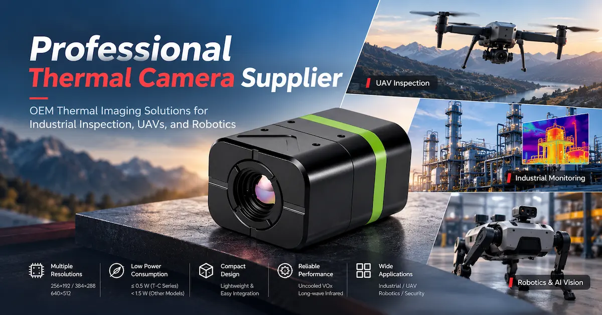
| T-C Series | 256×192 / 384×288 / 640×512 | ≤35 mK | ≤0.5 W | Multiple configurations; CVBS output and UART control |
| T256-S | 256×192 | ≤50 mK | <1.5 W | Compact module; separately specified lens and controller dimensions |
| T384-I | 384×288 | ≤50 mK | <1.5 W | Integrated form factor; 74 g published weight |
| T640-S | 640×512 | ≤50 mK | <1.5 W | Separately specified lens module and controller dimensions |
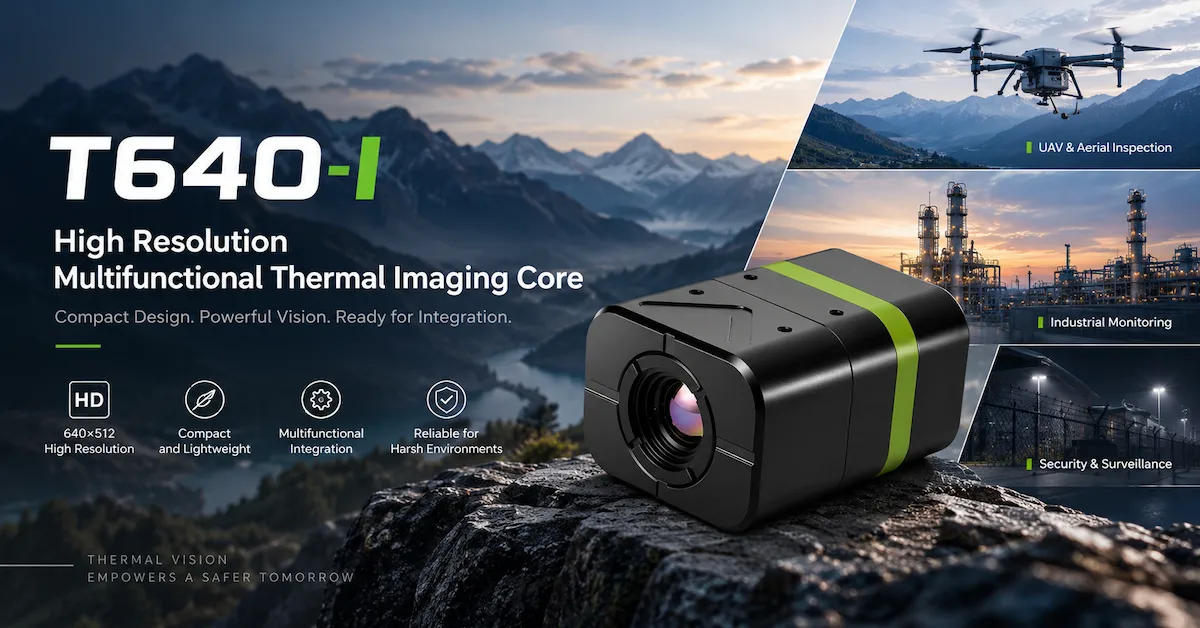
| T640-I | 640×512 | ≤50 mK | <1.5 W | Integrated 35×26×44 mm form factor; 63 g |
Source: EAGLET's published product specifications. NETD test conditions are not stated identically across every product series. Final values, configurations, and revisions must be confirmed before purchasing.
The published specifications describe uncooled vanadium oxide (VOx) detector technology, 12 μm detector pixel pitch, and 8–14 μm long-wave infrared spectral response.
The product pages also list CVBS (PAL) video output.
The T-C Series specifically publishes UART control information. Buyers should request the corresponding interface documentation for the exact model rather than assuming every module supports an identical control protocol.
Choosing the T-C Series for embedded development
The EAGLET T-C Series provides 256×192, 384×288, and 640×512 resolution options.
Its publicly stated characteristics include a 4.5–18 V input range, power consumption of no more than 0.5 W, and a compact mechanical configuration.
These specifications make it a candidate for evaluation where electrical power and installation space are important design constraints.
However, the final dimensions, weight, optical options, and electrical behavior should be confirmed for the exact requested configuration.
Evaluating T256-S and T384-I
The T256-S offers 256×192 imaging and a published 50 fps frame rate.
It may be considered where a lower-resolution imaging solution meets the target visibility requirements and the module's mechanical structure fits the intended equipment.
The T384-I provides 384×288 resolution in an integrated module measuring 35×26×49 mm according to its published specifications.
For some OEM products, the intermediate detector resolution may provide a practical balance between available image detail and the overall system architecture.
Neither module should be approved based solely on detector resolution.
Comparing T640-S and T640-I
Both the T640-S and T640-I publish 640×512 infrared resolution and 50 fps imaging.
Their mechanical arrangements differ.
The T640-S provides separate published dimensions for the lens module and main controller. The T640-I provides integrated overall dimensions and a stated weight of 63 g.
For an OEM engineer, that distinction can influence component placement, enclosure design, mounting brackets, cable routing, and the available space around other electronics.
Before deciding which architecture is more suitable, request the latest mechanical drawings, electrical documents, approved optical configuration, and relevant sample information.
Already comparing EAGLET modules for an OEM product? Explore the thermal imaging product range and submit your integration requirements for a model-specific discussion.
5. Resolution, Field of View, and Target Size: A Practical Selection Method
An infrared thermal camera factory may offer several detector resolutions, but resolution alone does not establish whether a camera will detect the object that matters to your application.
The key is understanding how the optical system distributes detector pixels across the scene.
Three common infrared detector configurations illustrate the difference.
| Thermal resolution | Detector pixels | Relative number of pixels |
|---|---|---|
| 256×192 | 49,152 | 1.00× |
| 384×288 | 110,592 | 2.25× |
| 640×512 | 327,680 | 6.67× |
A 640×512 detector contains approximately 6.67 times the pixels of a 256×192 detector.
That does not mean it can automatically detect an object 6.67 times farther away.
The useful result depends on the optics, target dimensions, thermal contrast, focus, atmosphere, image processing, and observation geometry.
5.1 Understand FOV before specifying resolution
Field of view describes how much of the scene the optical system captures.
A wide FOV covers a large area, which is useful when inspecting nearby equipment or monitoring several components from one installation point.
A narrower FOV allocates the detector's available pixels to a smaller angular region. That can be helpful when observing a smaller or more distant target.
For a simplified rectilinear optical model, the scene width at a given distance can be estimated as:
Scene width = 2 × Distance × tan(Horizontal FOV ÷ 2)
This equation provides a useful preliminary calculation when the intended working distance and lens field of view are known.
5.2 Worked example: observing a small component
Consider a hypothetical inspection application with these requirements:
-
Camera-to-target distance: 10 meters
-
Horizontal field of view: 40°
-
Target feature width: 100 mm
-
Required task: observe a localized feature within a larger scene
The approximate horizontal coverage is:
2 × 10 × tan(20°) ≈ 7.28 meters
The 100 mm target feature occupies approximately 1.37% of the scene width.
Assuming the same 40° optical field of view for each detector, its approximate horizontal pixel coverage would be:
| Detector resolution | Estimated horizontal pixels across 100 mm |
|---|---|
| 256×192 | 3.5 pixels |
| 384×288 | 5.3 pixels |
| 640×512 | 8.8 pixels |
These numbers are illustrative calculations, not measured EAGLET product results. They assume consistent optical coverage and simplified pixel mapping.
This example shows why selecting a detector based on the size of the target can be more useful than selecting the highest advertised resolution.
A feature occupying fewer than four pixels may still produce a visible thermal signal, but that does not mean its shape, identity, or temperature can be determined reliably.
The next question is whether the application requires simple thermal anomaly detection, target recognition, visual confirmation, or calibrated temperature measurement.
Each task may demand a different acceptance threshold.
5.3 Confirm the exact lens configuration
Before approving a thermal imaging module, request a revision-controlled specification covering focal length, horizontal and vertical FOV, IFOV where applicable, working distance, and focus.
The values should correspond to the same detector and lens assembly being supplied.
Do not combine the FOV from one optical configuration with the focal length or resolution of another.
For long-distance observation, a practical scene test using the intended target is more informative than an unspecified maximum detection-distance claim.
6. NETD, Image Quality, and Temperature Measurement Are Different Requirements
Infrared camera buyers often encounter thermal sensitivity values such as 35 mK or 50 mK.
These values refer to NETD, or Noise Equivalent Temperature Difference.
NETD describes the relationship between thermal signal response and image noise under specified measurement conditions. A lower value generally indicates better sensitivity to small thermal differences when comparing systems tested under equivalent conditions.
It does not directly tell the buyer whether a camera measures an object's absolute temperature accurately.
What should be checked when comparing NETD?
NETD can be affected by the optical aperture, detector operating conditions, measurement temperature, integration settings, and image processing.
Therefore, comparing two figures without their associated test conditions can produce misleading conclusions.
EAGLET's publicly detailed thermal cores include published values of ≤35 mK for the T-C Series and ≤50 mK for the other four listed core products. These should not be treated as directly comparable laboratory results without confirming the relevant methods.
For an OEM evaluation, request confirmation of the specific configuration and measurement conditions, particularly if the application depends on detecting small thermal differences.
Thermal imaging is not automatically radiometric thermography
An infrared imaging system may display thermal contrast without providing calibrated temperature values.
A quantitative temperature measurement system needs additional capabilities and validation, potentially including calibration, compensation for emissivity, reflected apparent temperature, distance, atmospheric effects, and measurement geometry.
This distinction is particularly important for industrial inspection and EV charging equipment.
For example, a camera may show that one electrical connector appears hotter than adjacent components. That information may support an inspection decision.
It does not automatically establish the connector's temperature to a specified measurement accuracy.
If the project requires temperature alarms at defined thresholds, the purchase specification should include the required measurement range, accuracy, calibration method, and radiometric output.
Do not assume these capabilities from detector resolution or NETD alone. EAGLET's public core specifications do not establish a universal calibrated measurement accuracy across the product range.
7. Video Interfaces and Embedded Integration: Avoiding Expensive Redesigns
One of the most consequential purchasing decisions involves the connection between the thermal core and the customer's existing electronics.
A module may satisfy the optical requirements and still be difficult to integrate if the host system does not support its video output.
7.1 CVBS is not a native digital image interface
The publicly listed EAGLET cores specify CVBS (PAL) video output.
CVBS is an analog composite video signal. It is not interchangeable with USB, MIPI CSI-2, Ethernet, or another native digital image interface.
A customer designing an embedded product with a digital image processor may require compatible analog video capture hardware or a different approved interface solution.
The infrared detector's native resolution should also be distinguished from the signal ultimately delivered through the video chain.
For example, a 640×512 detector does not automatically mean the final host receives uncompressed 640×512 digital thermal data through CVBS.
An OEM engineer should validate the actual captured image and the host processing requirements before approving the module.
7.2 Confirm control commands independently
The T-C Series publishes UART control support.
For any module requiring remote settings, shutter commands, image palette changes, or other control functions, request the applicable command documentation.
The factory and buyer should verify which commands are supported by the actual hardware and firmware version.
Do not assume that similar-looking connectors use the same pin assignment or control protocol.
7.3 Measure the complete imaging chain
A thermal imaging system may involve several stages:
Infrared acquisition → onboard processing → video output → host capture → encoding → transmission → decoding → display
Each stage can affect total latency.
Several EAGLET product pages publish imaging latency below 20 ms. That figure should not be interpreted as a guarantee for an entire UAV video link, industrial monitoring network, or remote control system.
For real-time equipment, measure performance using the complete intended architecture.
This is especially important when the thermal image is used by an operator controlling a moving platform.
7.4 Electrical and mechanical requirements
Before a module enters the final enclosure design, the factory should confirm:
| Integration parameter | Buyer verification |
|---|---|
| Input voltage | Compatible with the intended power supply |
| Operating power | Suitable for the product's electrical and thermal budget |
| Startup behavior | Acceptable current demand and initialization sequence |
| Video output | Compatible with the receiving hardware |
| Control interface | Required commands and protocol confirmed |
| Connector and pinout | Correct mechanical and electrical arrangement |
| Module dimensions | Fits the enclosure and mounting location |
| Cable arrangement | Suitable routing, shielding and strain relief |
| Heat dissipation | Stable operation in the assembled device |
| Firmware revision | Identified and documented for repeat procurement |
A low-power module may still experience unwanted heating when installed beside a processor, motor controller, battery, or another heat-generating component.
System-level testing is therefore necessary even when the published module power consumption appears suitable.
For model-specific technical questions, buyers can use EAGLET's product and integration support page.
8. Matching Infrared Thermal Cameras to Real Industrial Applications
The most useful factory discussions begin with the operating environment.
An infrared module selected for a stationary electrical inspection system may be unsuitable for an aircraft-mounted camera, even when the two products use the same detector resolution.
8.1 Industrial electrical and machinery inspection
Thermal imaging can help operators observe temperature distribution and identify potentially abnormal thermal patterns.
Common equipment includes electrical panels, power distribution assemblies, machinery, motors, and industrial components.
For manufacturers building this type of equipment, the critical requirements may include target size, working distance, installation angle, thermal contrast, repeatability, and integration with an inspection interface.
Where the purpose is temperature measurement rather than visual anomaly detection, buyers must verify radiometric functionality separately.
EAGLET provides an industrial inspection solution overview that can serve as an application starting point.
8.2 EV charging and new-energy equipment
Charging connectors, power conversion equipment, and related electrical infrastructure can develop abnormal heating under certain conditions.
Thermal imaging may support non-contact observation or inspection workflows.
However, a working temperature alarm system requires more than detecting a bright region in a thermal image.
The engineering team must consider the operating load, environmental conditions, component materials, reflected radiation, alarm strategy, and required measurement reliability.
For outdoor charging equipment, enclosure design, weather exposure, and installation geometry may create additional validation requirements.
The EAGLET new-energy solution page introduces this application direction.
8.3 UAV and airborne thermal imaging
A drone thermal camera module must fit within the payload's physical and electrical limitations.
Important considerations include mechanical layout, electrical power, total payload mass, operating temperature, frame rate, field of view, and video transmission compatibility.
A split lens-and-controller architecture may provide a different installation layout from an integrated module. Whether this is beneficial depends on the payload design.
Higher resolution can be useful when targets occupy a small portion of the field of view, but it should be assessed together with the intended altitude, lens configuration, and operating conditions.
OEM teams can review EAGLET's UAV and low-altitude imaging solutions when defining their initial system requirements.
8.4 Robotics and embedded machine vision
Autonomous inspection equipment may need thermal imagery alongside visible-light cameras, navigation sensors, and embedded processors.
Integration requirements can include startup sequencing, control commands, image synchronization, and continuous operation.
For these products, a factory's ability to provide accurate interface documentation and support engineering discussions may be more valuable than a large list of general imaging features.
8.5 Security and low-light observation
Long-wave infrared imaging can support observation in darkness without relying on visible illumination.
However, thermal cameras do not literally see through walls. Ordinary window glass can also block or reflect long-wave infrared radiation, affecting what the camera observes.
Heavy precipitation, atmospheric conditions, reflective surfaces, and some forms of smoke or airborne contamination may reduce image quality.
Security equipment manufacturers should therefore verify target visibility under representative environmental conditions rather than assuming that thermal imaging performs equally well in all situations.
9. What Quality Control Should an Infrared Thermal Camera Factory Demonstrate?
Quality control should be connected to the characteristics that matter in the finished device.
A production process that identifies obvious electrical faults but does not verify imaging performance may be insufficient for an industrial thermal imaging module.
The following framework shows what buyers can request during supplier evaluation.
9.1 Incoming material and component checks
A documented incoming process may assess detector components, optical assemblies, electronic boards, connectors, and other relevant purchased parts.
Depending on the manufacturing arrangement, verification might include supplier documentation, physical inspection, component identification, or defined functional checks.
The most important purchasing question is how unsuitable materials are prevented from entering approved production.
9.2 Optical and mechanical assembly checks
Optical integration affects image sharpness and usable field of view.
Assembly errors may result in defocus, misalignment, mechanical interference, contamination, or inconsistent results between units.
The supplier should explain which properties are controlled and how production operators determine that the assembly meets the approved specification.
9.3 Electrical and image-function testing
For an embedded infrared module, suitable end-of-line checks may include:
-
Module startup and video output
-
Power consumption under specified conditions
-
Interface and supported control functions
-
Image stability and abnormal artifacts
-
Shutter or non-uniformity correction behavior, where applicable
-
Optical focus and field coverage
-
Product configuration and revision identification
These are recommended verification items, not confirmed descriptions of EAGLET's current factory procedures.
9.4 Environmental and reliability assessment
A published operating temperature range is a useful reference, but it does not independently establish performance in every finished enclosure or application.
A camera operating inside an industrial cabinet may experience different conditions from one mounted on an exposed UAV.
Appropriate validation may include temperature cycling, sustained operation, vibration, mechanical retention, and other tests relevant to the finished product.
The specific test standards, limits, durations, and acceptance criteria should be agreed upon rather than assumed.
9.5 Batch consistency and corrective actions
For recurring orders, one of the most valuable supplier capabilities is identifying the cause of a failure and preventing its recurrence.
The customer should understand how the factory manages nonconforming units, production records, batch identification, and approved design changes.
Ask what information can be traced if a defective module is discovered after integration into a finished product.
Without a defined process, a technical issue can become a commercial problem involving rework, delayed production, replacement parts, and customer complaints.
10. Sample Acceptance Testing Before Volume Procurement
Sample testing should answer one practical question:
Does this exact infrared module configuration meet the requirements of the product we intend to manufacture?
The test plan should be written before evaluation begins.
A sample that looks satisfactory during an informal demonstration may fail when connected to the actual host controller or installed inside the intended enclosure.
Recommended OEM sample acceptance matrix
| Test area | Test method | Evidence to retain |
|---|---|---|
| Product identification | Match sample and documentation to approved configuration | Model, revision and configuration records |
| Electrical compatibility | Operate using intended supply and host electronics | Voltage, current and startup observations |
| Video integration | Capture the output using the intended receiving hardware | Recorded images and interface results |
| Optical coverage | Observe representative targets at planned distances | FOV and target visibility records |
| Thermal imaging performance | Test relevant thermal scenes and contrast conditions | Images, settings and environmental conditions |
| Mechanical fit | Install within representative mounting geometry | Clearance, installation and assembly results |
| Continuous operation | Run for a duration appropriate to the application | Faults, stability and temperature observations |
| System latency | Test the complete intended image path | Measured end-to-end behavior |
The matrix should also identify the required acceptance limits, measurement equipment, test conditions, responsible parties, and rules for handling failed results.
For example, an industrial equipment manufacturer may define a minimum number of thermal pixels across a critical component.
A UAV manufacturer may define a maximum acceptable installed payload mass and a system-level video delay requirement.
These criteria should be established by the customer's design team rather than invented by the supplier.
Three stages of validation
Engineering sample: Confirm whether the selected thermal imaging architecture is technically suitable.
Integrated prototype: Verify the module within the actual enclosure, electronics, firmware, and application conditions.
Pilot production: Check whether the approved configuration can be reproduced consistently under the intended purchasing and manufacturing arrangements.
A successful first sample is an important milestone, but it does not automatically qualify every subsequent production batch.
11. OEM/ODM Customization: What Should Be Agreed Before Development?
Customization often creates the strongest reason to work with an infrared thermal camera factory rather than purchasing a finished standard camera.
EAGLET publicly describes OEM/ODM support involving resolution options, lens selection, interfaces, housing, software, and broader system integration.
These are areas for project discussion; the feasibility and commercial scope of a particular modification must be confirmed individually.
Resolution and optical configuration
A customer may need a different balance between imaging detail, field coverage, installation dimensions, and electrical power.
The first engineering step should be an application requirement rather than a predetermined detector specification.
Mechanical integration
Custom products may require changes in mounting arrangements, enclosure geometry, cable access, or component positioning.
Mechanical drawings should be exchanged before a design is released for tooling or fabrication.
Interface and software requirements
A buyer may require compatibility with an existing controller or processing architecture.
Potential custom interface requirements should be discussed early, including the availability of the necessary hardware, firmware, protocols, and documentation.
An interface mentioned as a customization direction should not be treated as a standard feature of every product model.
Intellectual property and design ownership
Custom development arrangements should clarify which party owns the customer-specific design files, tooling, firmware modifications, and technical deliverables.
Where confidentiality or exclusivity matters, the commercial agreement should define those responsibilities.
Do not assume that OEM customization automatically grants exclusive rights to the underlying imaging technology.
Engineering change control
A reliable customization project needs a method for approving changes after the initial design.
Without defined responsibilities, a seemingly minor adjustment to the lens, board, or interface may alter validated product performance.
Buyers should agree on revision identification, testing responsibilities, approval requirements, and the process for introducing changes into future orders.
12. Factory Price vs Total OEM Integration Cost
A unit quotation is only one part of the overall cost of sourcing thermal imaging hardware.
For professional equipment manufacturers, the full cost may include engineering, optical integration, electronics, qualification, documentation, mechanical design, and long-term support.
| Cost component | Potential purchasing impact |
|---|---|
| Imaging core | Base hardware and selected configuration |
| Optics | Lens selection and application-specific field coverage |
| Interface hardware | Additional video acquisition or conversion components |
| Engineering integration | Mechanical design, firmware and host compatibility |
| Prototype testing | Samples, test fixtures and technical evaluation |
| Customization | Development, tooling or configuration changes |
| Quality requirements | Agreed inspection, test and documentation scope |
| Logistics and compliance | Shipping, applicable import requirements and approvals |
| Product maintenance | Spare units, future revisions, replacement arrangements |
For example, a lower-priced module might require an additional video conversion board, new firmware development, or changes to a mechanical enclosure.
Another module with a higher initial quotation might fit the intended system with fewer integration changes.
The correct decision depends on the total project requirements, not on a universal assumption that one configuration is cheaper.
Commercial questions worth resolving early
Before committing to a factory, confirm the quotation's exact scope and the conditions under which pricing changes.
Ask whether the quoted price includes the specified lens, controller, connector accessories, documentation, testing arrangements, and any agreed customization.
MOQ, sample lead time, production lead time, payment terms, Incoterms, warranty terms, and engineering charges should be confirmed directly.
These commercial conditions are project-specific and should not be inferred from generic statements about factory capability.
If a project requires long-term purchasing, include a process for handling discontinued parts and proposed substitutions.
13. Compliance and Risk Management for International Buyers
International OEM customers should evaluate compliance based on the final equipment and its intended market.
A thermal imaging core incorporated into an industrial monitoring product may have different compliance responsibilities from a finished handheld measuring instrument.
The relevant requirements may involve electrical safety, electromagnetic compatibility, environmental protection, product documentation, and applicable import or export controls.
For example, IEC 60529 addresses degrees of protection provided by enclosures. An IP rating applies to a defined enclosure configuration and does not automatically follow from the internal thermal imaging module.
Likewise, a supplier's general quality management claims should not be treated as evidence of a particular ISO certification without confirming the certificate's validity and scope.
Some thermal imaging products may also be subject to export-control classifications or licensing requirements depending on technical characteristics, destinations, and applicable law.
International buyers should verify the requirements relevant to the proposed transaction.
Four avoidable purchasing risks
Unverified performance claims: Request evidence tied to the exact proposed model and operating conditions.
Uncontrolled engineering changes: Agree on hardware, firmware, optical configuration, and notification requirements.
Unclear documentation: Establish which technical materials will be available during development and after production begins.
Misaligned commercial expectations: Confirm MOQ, lead time, warranty, customization costs, and delivery responsibilities in writing.
A technically promising product can still create significant procurement risk if these matters remain unresolved.
14. Why Consider EAGLET for an OEM Thermal Imaging Project?
EAGLET's publicly presented business focus includes infrared thermal imaging cores and integrated intelligent vision solutions.
Its company profile describes activities spanning sensing, image processing, embedded hardware, laboratory validation, and manufacturing.
The website also provides office and factory locations in Shenzhen, China.
For OEM buyers, several aspects of this positioning are relevant.
An identifiable thermal imaging core portfolio
The company publishes named thermal imaging core models with detector resolutions ranging from 256×192 to 640×512.
This allows buyers to begin technical comparisons using specific product information instead of relying entirely on broad manufacturer claims.
Application-oriented engineering discussions
The company's published application directions include industrial inspection, UAV systems, robotics, security, and other professional imaging uses.
These areas provide starting points for discussing optical coverage, system interfaces, installation constraints, and other application requirements.
Multiple integration considerations
Published product information includes different module configurations, power requirements, resolution options, and mechanical arrangements.
This may be useful for manufacturers seeking an embedded imaging solution rather than an off-the-shelf consumer device.
A defined project inquiry process
EAGLET requests information about the intended application, performance targets, resolution, lens, interface, power, environmental requirements, dimensions, and expected purchasing quantity.
That approach gives engineering teams a clearer starting point for model selection and customization discussions.
However, website information should always be supplemented with the relevant revision-specific documents, commercial terms, and sample validation results.
A prospective customer should still carry out the appropriate technical and supplier evaluation before approving production.
Planning an industrial thermal inspection instrument, robotic vision platform, or UAV payload? Contact EAGLET's team with your application and integration requirements to discuss an appropriate thermal imaging core or OEM configuration.
15. A Practical RFQ Checklist for Infrared Thermal Camera Factory Buyers
A useful request for quotation should enable the supplier to understand both the intended imaging task and the purchasing scope.
Sending only “Please quote your best price for a 640×512 thermal camera” is unlikely to provide enough information for a dependable OEM proposal.
A more useful inquiry includes:
| RFQ field | Information to provide |
|---|---|
| Product application | Industrial inspection, UAV, robotics, monitoring or other equipment |
| Required product scope | Thermal imaging core, module or complete system |
| Detector resolution | Preferred specification or acceptable alternatives |
| Observation requirements | Target type, dimensions and working distance |
| Optical requirements | Required FOV, lens arrangement or installation geometry |
| Imaging performance | Thermal contrast needs, frame rate and latency |
| Temperature measurement | Whether calibrated radiometric measurement is mandatory |
| Electrical system | Available supply voltage and power limitations |
| Video and control | Required interfaces, protocols and host electronics |
| Mechanical requirements | Maximum dimensions, mounting conditions and weight |
| Operating environment | Temperature, vibration, enclosure and exposure conditions |
| Documentation | Required datasheets, drawings and interface information |
| Purchasing volume | Sample quantity, pilot quantity and estimated annual demand |
| Commercial requirements | Destination, requested delivery terms and project schedule |
Buyers should identify which requirements are mandatory and which remain open to engineering alternatives.
For example, a particular connector may be mandatory if the customer's control board is already finalized. Detector resolution may be flexible if the required target visibility can be achieved with another approved optical arrangement.
That distinction can reduce unnecessary customization and make the supplier's technical response more useful.
Use the EAGLET contact and RFQ page to submit the available project details. Exact technical documentation can also be requested through the support page.
16. Frequently Asked Questions
Is an infrared thermal camera factory the same as an infrared detector manufacturer?
No. An infrared detector manufacturer specializes in detector components and related technologies, while a thermal camera factory may integrate detectors with optics, electronics, firmware, mechanical assemblies, and testing processes.
Some companies cover multiple stages of this value chain.
OEM buyers should ask which activities the supplier performs directly and which components or processes are sourced externally. This distinction helps clarify engineering responsibility and production control.
What is the difference between a thermal imaging core and a finished thermal camera?
A thermal imaging core provides the fundamental infrared imaging function and associated integration interfaces.
A finished camera generally incorporates additional elements such as a housing, power system, display or communication hardware, control software, and application-specific functions.
For OEM equipment development, a core can provide greater flexibility because the customer can integrate it into a proprietary device. However, additional engineering may be required.
Which detector resolution should an OEM buyer choose?
The appropriate resolution depends on the target size, observation distance, optical field of view, and required imaging task.
A 256×192 module may be adequate for certain close-range monitoring applications, while 384×288 or 640×512 can provide additional detector pixels for applications requiring more potential detail.
Resolution alone cannot determine the result. Buyers should calculate target pixel coverage and validate the proposed lens-and-detector configuration with representative samples.
Can an infrared thermal camera measure temperature accurately?
Some infrared cameras are designed for calibrated radiometric temperature measurement, but not every thermal imaging core provides that capability.
NETD describes thermal sensitivity rather than absolute measurement accuracy.
If a project requires temperature readings or threshold alarms, request the measurement range, accuracy specification, calibration information, and necessary output interfaces for the exact system.
Do not assume measurement functionality from an image display alone.
How can I verify a thermal camera factory's quality control?
Ask for documentation explaining relevant production and inspection controls, product identification, end-of-line tests, and the procedure for handling nonconforming units.
Where the project justifies it, conduct a factory audit or arrange an appropriate third-party assessment.
The supplier should also clarify how it manages component substitutions and product revisions.
An attractive sample image is not sufficient evidence of manufacturing consistency.
Does a 640×512 thermal core automatically provide 640×512 digital video output?
No. Infrared detector resolution and external video output format are separate specifications.
For example, EAGLET's published T640-S and T640-I product pages list 640×512 detectors and CVBS (PAL) output.
OEM buyers should confirm the actual delivered video signal, receiving hardware, processing requirements, and whether a suitable digital interface or conversion path is available.
Can EAGLET support custom infrared thermal imaging development?
EAGLET publicly describes OEM/ODM support involving thermal imaging modules, resolution selection, optics, interfaces, mechanical integration, and software-related requirements.
The availability of a specific customization depends on the selected product, engineering feasibility, project scope, and commercial agreement.
Buyers should submit the intended application and technical requirements to obtain a model-specific assessment rather than assuming that every product supports the same modifications.
What should overseas importers check before ordering thermal cameras in bulk?
Importers should establish the exact product specification, sample acceptance criteria, intended market requirements, applicable compliance documentation, MOQ, production lead time, warranty arrangements, and shipping terms.
For OEM products, configuration consistency and change control are especially important.
A pilot order or controlled initial batch may be appropriate before establishing larger repeat purchases.
Conclusion
Selecting the right infrared thermal camera factory requires a clear understanding of both manufacturing responsibilities and the technical demands of the finished product.
For OEM manufacturers, system integrators, and industrial equipment buyers, the strongest supplier evaluation combines five elements: verified product specifications, suitable optical and electrical integration, documented manufacturing controls, application-specific sample testing, and clearly defined commercial responsibilities.
Detector resolution, NETD, frame rate, and power consumption are important, but none should be assessed in isolation. The correct thermal imaging core must also match the intended target, operating distance, field of view, installation geometry, host electronics, and environmental conditions.
EAGLET provides a published portfolio of uncooled infrared thermal imaging cores, including the T-C Series, T256-S, T384-I, T640-S, and T640-I, alongside OEM/ODM integration discussions for professional imaging applications.
If you are developing an industrial inspection instrument, embedded thermal camera, robotic vision system, or UAV imaging payload, begin with the actual engineering requirements rather than a generic product quotation.
Explore EAGLET Thermal Imaging Products to compare available module configurations, or Contact EAGLET for an OEM Thermal Imaging Consultation to discuss your application, interface requirements, preferred resolution, and purchasing plans.
A well-defined technical discussion today can help avoid incompatible components, unnecessary engineering changes, and preventable production problems later.