
What Should an Infrared Imaging Camera Manufacturer Deliver for an OEM Project?
An infrared imaging camera manufacturer should help you specify a complete imaging path: the appropriate infrared technology, a detector-and-lens combination that resolves your target, compatible video and control interfaces, and a configuration that can be validated inside your finished equipment.
For an OEM project, a clear demonstration image is only the starting point. Your product may need to observe a small electrical connection, display a usable scene from a moving inspection robot, or transmit thermal video from an airborne payload. Each task requires a different balance of image detail, coverage, integration effort, and operating constraints.
The practical purchasing objective is therefore straightforward: buy the imaging capability your system needs, not an isolated specification that looks impressive on a datasheet.
This guide concentrates on engineering selection for uncooled long-wave infrared imaging. It is intended for equipment manufacturers, product engineers, and system integrators developing their own infrared devices—not buyers seeking a ready-to-use consumer camera.
EAGLET’s infrared imaging products for OEM integration include thermal cores with several detector resolutions and mechanical configurations. The following framework explains how to connect those product options to an actual design requirement. EAGLET
1. Confirm Whether Your Project Needs Thermal Imaging or Another Infrared Technology
“Infrared camera” does not describe a single interchangeable technology. Before selecting an infrared imaging camera manufacturer, establish what creates the contrast your system needs to observe.
Reflected Infrared Light and Thermal Emission Serve Different Tasks
Near-infrared imaging can use reflected infrared illumination to reveal a scene. A camera operating with an infrared illuminator is not automatically a thermal camera.
Short-wave infrared, or SWIR, is also commonly used for reflected-light and material-contrast imaging. For example, inspection tasks may exploit how a material reflects, absorbs, or transmits particular wavelengths.
Thermal imaging instead uses infrared radiation to reveal thermal contrast. Long-wave infrared cameras can provide images without visible illumination, but their usefulness still depends on the target, background, optics, and operating conditions.
This distinction matters when your development brief says only “night vision” or “infrared inspection.” Those descriptions do not establish the required detector technology.
| Project objective | Technology question to resolve | Purchasing implication |
|---|---|---|
| Observe a scene with infrared illumination | Is reflected-light imaging sufficient? | Confirm illumination, sensor response, and optics |
| Inspect wavelength-dependent material contrast | Does the task require a specific SWIR band? | Select the sensor and optical components around that band |
| Observe thermal differences without visible lighting | Is an LWIR thermal imaging core appropriate? | Evaluate thermal sensitivity, optics, and delivered image quality |
| Produce numerical temperature readings | Is calibrated radiometric output available? | Require measurement specifications beyond image quality |
EAGLET’s five core product entries discussed below specify uncooled VOx detectors operating in the 8–14 μm LWIR range. This is the documented starting point for the comparison; it should not be interpreted as a claim that these models provide SWIR imaging or calibrated temperature measurement. EAGLET
Know When the Product Family Is Not the Right Starting Point
Do not force an available thermal module into a requirement defined around a different spectral band.
Similarly, a project requiring a particular digital image interface should not assume that a module with analog video can connect directly. A measurement-based project should not proceed on the assumption that every thermal image contains accessible, calibrated temperature data.
Resolving these questions before sample purchasing makes the later technical discussion more productive.
2. Translate the Application into an Imaging Requirement
A useful project brief describes the target and the decision the camera must support. “High resolution, low power, and good image quality” does not provide enough information to select a configuration.
Ask your engineering team to complete this sentence:
“Our system must observe or measure [target] at [distance], while covering [area], and deliver [image or data] to [host equipment].”
That single statement connects the application to optics, electronics, and acceptance testing.
Industrial and Energy Equipment
For an inspection device, distinguish between observing an entire equipment bay and examining a small connection within it.
A broad thermal view may help an operator locate an unusual heat pattern. Evaluating a small component requires enough spatial detail at the installed distance. A numerical temperature alarm adds separate radiometric and application-validation requirements.
When discussing thermal imaging for industrial inspection, provide target dimensions, mounting restrictions, operating loads, and the required output. Describe whether a person will interpret the image or whether software must act on it.
UAVs and Mobile Inspection Platforms
For airborne or mobile equipment, specify the complete payload allowance rather than only the desired camera-core weight.
Your allocation should account for the lens, mounting hardware, enclosure, cables, interface electronics, and any transmission equipment included in the design. Define the working distance and observation angle, not merely the aircraft’s nominal altitude.
EAGLET’s UAV and low-altitude imaging solutions provide a relevant application route for discussing these requirements.
Define the Acceptance Task Before Choosing the Model
Separate three objectives: detecting that a target is present, obtaining enough detail to classify it, and measuring its temperature. Passing one objective does not prove the others.
For example, an industrial robot could display an obvious hot region without resolving the small component responsible for it. The project should specify whether this result is acceptable.
A capable infrared imaging camera manufacturer should respond to that defined task, rather than replace it with a generic maximum-distance claim.
3. Match Resolution, Pixel Pitch, and Lens Focal Length
Detector resolution matters, but it must be evaluated alongside the optical configuration.
At the same pixel pitch and lens focal length, increasing the detector’s pixel count primarily increases scene coverage; it does not automatically increase the number of pixels across the same target.
This is an important distinction for OEM teams comparing 256 × 192, 384 × 288, and 640 × 512 cores.
Understand FOV and IFOV
Field of view, or FOV, describes the overall scene captured by the camera.
Instantaneous field of view, or IFOV, describes the angular portion associated with one detector pixel. For a small-angle estimate near the optical axis:
IFOV in radians ≈ pixel pitch ÷ focal length
Both dimensions must use the same units. At a specified distance:
Projected pixel width ≈ distance × IFOV
These relationships help screen an optical concept before ordering samples. They do not establish actual recognition performance, optical sharpness, or temperature measurement accuracy.
An Illustrative Target-Pixel Calculation
Consider a hypothetical target that is 100 mm wide and 20 m from the camera. Assume 12 μm pixels, an appropriately matched lens, and an unobstructed view near the image center.
| Illustrative configuration | Detector resolution | Lens focal length | Approximate projected pixel width | Pixels across the 100 mm target |
|---|---|---|---|---|
| A | 256 × 192 | 12 mm | 20 mm | 5 |
| B | 640 × 512 | 12 mm | 20 mm | 5 |
| C | 640 × 512 | 24 mm | 10 mm | 10 |
These are calculation examples, not EAGLET product configurations, available lens options, measured results, or guaranteed detection distances.
Configurations A and B place approximately the same number of pixels across the target. The larger detector in B provides broader coverage when the optics support its full image area.
Configuration C allocates more pixels to the target by using a longer focal length. The trade-off is narrower coverage compared with B.
This explains why a higher-resolution purchase can disappoint when the lens selection is left unchanged and the buyer expects more distant-target detail.
Turn the Calculation into a Purchase Decision
Ask the manufacturer to propose a detector-and-lens combination against both your coverage requirement and minimum target size.
Then verify the delivered image using representative targets. Focus, optical quality, thermal contrast, signal processing, and the downstream video path still matter.
For quantitative thermography, request the manufacturer’s measurement-field requirements. A target’s geometric pixel coverage alone does not prove that a temperature reading is accurate.
4. Read NETD and Radiometric Specifications as Different Requirements
When evaluating an infrared imaging camera manufacturer, separate thermal sensitivity, spatial detail, and temperature measurement accuracy.
These specifications answer different questions.
NETD Describes Sensitivity Under Stated Conditions
Noise Equivalent Temperature Difference, or NETD, characterizes the ability to distinguish small thermal differences relative to noise.
A lower value generally indicates better sensitivity when the measurement conditions are comparable. However, lens aperture, optical transmission, scene temperature, and processing conditions can influence the result.
For procurement, request the test conditions with the number. An unqualified “35 mK” should not be treated as a complete comparison against a specification measured at a stated temperature and aperture.
Also ask whether the quoted value describes the detector, an imaging core, or a complete configured system.
A Thermal Image Is Not Automatically a Temperature Dataset
A camera may deliver a useful image of thermal contrast without supplying calibrated temperature values.
For measurement-based applications, request the supported measurement range, accuracy conditions, calibration method, compensation parameters, and accessible output data.
Emissivity, reflected radiation, atmospheric transmission, and the camera’s thermal state can affect temperature interpretation. A factory specification must therefore be considered alongside the actual installation and measurement procedure.
The published EAGLET core specifications cited in this guide do not provide a complete radiometric measurement specification. Do not assign these models a temperature accuracy, measurement range, or automatic alarm capability that has not been confirmed.
For an observation project, this distinction helps avoid purchasing unnecessary functions. For a measurement project, it prevents approving hardware before an essential requirement is resolved.
5. Verify the Image Your Host System Will Actually Receive
A purchasing specification should describe the delivered signal—not simply the detector behind it.
The five EAGLET core entries compared below list CVBS (PAL) video output. The T-C Series also explicitly lists UART control. EAGLET
Keep Detector Resolution Separate from Video Format
A 640 × 512 detector does not mean that its output connector supplies a native 640 × 512 digital image stream.
CVBS is analog composite video. Where the host requires digital input, a compatible capture or conversion path must be defined and validated.
Before approving the design, ask what the host will receive: a display-ready thermal image, processed pixel data, or calibrated temperature data. Do not treat those outputs as equivalent.
An infrared imaging camera manufacturer should confirm the actual signal format, connector definition, electrical requirements, and control functions for the selected revision.
Evaluate the Complete Timing Path
Frame rate describes image update frequency. Latency describes elapsed time through a specified processing path.
A published core latency cannot establish the performance of a complete system that also includes conversion, encoding, transmission, decoding, and display.
Define where your latency test starts and ends. For a remote inspection product, measure the image presented to the operator using the intended host and communication equipment.
Also confirm whether the stated imaging rate refers to detector acquisition, internal processing, or the delivered video format. Specifications expressed as hertz and frames per second should not be assumed to describe identical points in the signal chain.
Specify Control Behavior, Not Just a Port Name
Request the command set, startup behavior, supported modes, and response behavior needed by your application.
For example, define what the host should do after a power interruption or loss of communication. Record which settings must persist and which must be restored.
The model-specific integration documentation available through EAGLET is matched to the confirmed product model and revision. Use that documentation to finalize the interface, rather than transferring assumptions from another module. EAGLET
6. Compare EAGLET’s Published LWIR Core Options
EAGLET provides several documented starting points for embedded thermal imaging projects. The following table summarizes selected published parameters without treating every model as interchangeable.
| Product | Detector resolution | Published NETD | Published power consumption | Input voltage |
|---|---|---|---|---|
| T-C Series thermal imaging core | 256 × 192 / 384 × 288 / 640 × 512 | ≤35 mK | ≤0.5 W | 4.5–18 V |
| T256-S compact infrared core | 256 × 192 | ≤50 mK at 25°C, F/1.0 | <1.5 W | 9–24 V |
| T384-I thermal imaging module | 384 × 288 | ≤50 mK at 25°C, F/1.0 | <1.5 W | 9–24 V |
| T640-S high-resolution infrared core | 640 × 512 | ≤50 mK at 25°C, F/1.0 | <1.5 W | 9–24 V |
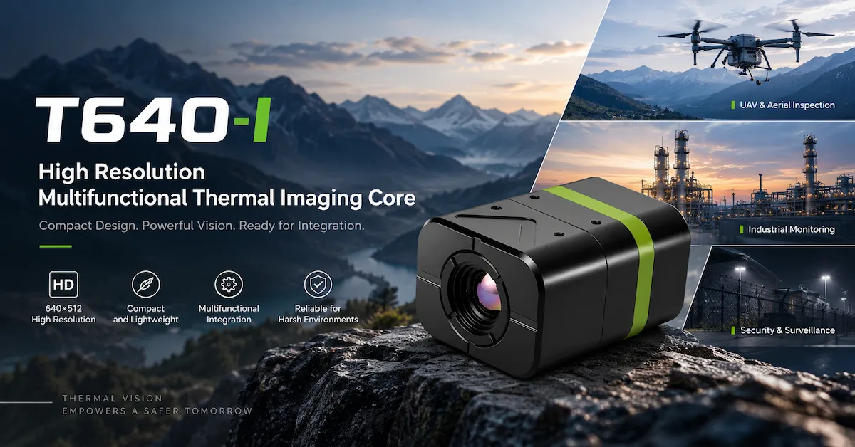
| T640-I integrated thermal imaging core | 640 × 512 | ≤50 mK at 25°C, F/1.0 | <1.5 W | 9–24 V |
Figures are from the linked product pages. The T-C Series NETD entry does not state the same test conditions shown for the other four products, so the table is not a controlled performance ranking. Confirm the selected configuration and current technical documents before design approval. EAGLET
A Starting Point for Low-Power Requirements
The T-C Series lists three resolution configurations: T-C2, T-C3, and T-C6. Its published power and supply range make it a candidate to investigate when the electrical budget is a primary constraint.
Qualification should still include the required lens, operating modes, startup behavior, and the power consumed by other system components.
Options for Separated Camera-Head and Controller Placement
The T256-S and T640-S pages provide separate dimensions for their lens modules and main controllers. This makes them relevant to a layout review where the optical opening and electronics compartment cannot occupy the same space.
Confirm the supplied interconnection, permitted routing, mounting details, and configuration before relying on that arrangement.
Integrated Modules for Mechanical Comparison
The T384-I publishes dimensions of 35 × 26 × 49 mm. The T640-I publishes 35 × 26 × 44 mm.
These dimensions provide an initial mechanical comparison, not a substitute for drawings showing connectors, lens clearance, and mounting features.
Use the table to create a shortlist; use application evidence to approve the selection. Resolution and module dimensions alone do not determine which product is best for your design.
7. Design the Enclosure and Installation Around the Optical System
The enclosure is part of the imaging design. Ask the infrared imaging camera manufacturer to review the optical opening and installation concept before the mechanical design is released.
Specify Window and Lens Requirements Explicitly
Do not assume that a cover material suitable for a visible-light camera is suitable for the intended infrared band.
Request spectral transmission information for any protective window, together with coating, thickness, mounting, and environmental requirements. Ask whether the proposed lens-and-window combination needs separate validation or calibration.
Likewise, do not assign a specific optical material to an EAGLET model unless its documentation identifies that material. An exterior product image cannot establish lens composition or coating performance.
Account for Local Heating and Installation Stress
Define the temperatures expected around the camera, not only the room or outdoor ambient temperature.
For measurement-based systems, changes in camera-body or optical temperature can influence uncertainty. Include the installed configuration in evaluation rather than qualifying only a bare module.
Your mechanical review should also cover cable strain relief, mounting repeatability, service access, and the ability to replace a module without losing the approved optical alignment.
Treat Environmental Performance as a System Requirement
Ask for evidence applicable to the exact assembly when the project requires resistance to dust, water, vibration, or electromagnetic disturbance.
Do not carry a finished-camera rating over to a board-level core, or assume that an enclosure automatically qualifies the electronics installed inside it.
For outdoor projects, define how acceptable images will be assessed under the relevant weather and background conditions. A general application label is not an acceptance test.
8. Plan OEM Development Around Measurable Approval Gates
The following workflow is a proposed purchasing and development framework, not a claim that every EAGLET project follows an identical schedule.
Gate 1: Confirm Feasibility Before Custom Development
Provide the target task, host interface, optical coverage, available space, and power budget.
Request a standard-product option first. Where it cannot satisfy a mandatory requirement, identify the exact customization needed.
This separates necessary engineering from preferences that may add cost without improving the application.
Gate 2: Agree on Engineering Responsibilities
Define who supplies the optics, mounting hardware, host electronics, software integration, and finished-product testing.
For customized work, document deliverables and acceptance criteria. Discuss ownership and confidentiality before exchanging proprietary design information.
EAGLET describes an integration-oriented scope spanning thermal sensing, image processing, embedded hardware, and customized vision applications on its company and engineering capabilities page. The specific work package should be confirmed for each project. EAGLET
Gate 3: Validate the Installed Prototype
Use the camera inside a representative mechanical and electrical assembly.
| Validation area | Evidence to capture |
|---|---|
| Target visibility | Images of the actual target at required distances and backgrounds |
| Optical coverage | Confirmation that the scene and target detail both meet the brief |
| Host compatibility | Successful operation with the intended video and control path |
| Power behavior | Startup and operating measurements in required modes |
| Timing | End-to-end results using the defined test endpoints |
| Installed operation | Performance during the relevant operating and environmental conditions |
Keep test conditions with the results. A screenshot without the target distance, lens configuration, and processing settings has limited value for repeat comparison.
Gate 4: Release an Approved Production Configuration
Record the model, optics, hardware revision, firmware, accessories, and acceptance criteria.
For repeat orders, agree on how changes affecting those items will be communicated and reviewed. Any required certificates or test reports should identify the relevant product or organization; a general quality statement is not equivalent evidence.
The thermal camera supplier qualification guide covers the broader supplier-approval process. Keep this project’s technical release tied to the exact imaging configuration.
9. Compare Complete Engineering Cost, Not Only Module Price
The quotation from an infrared imaging camera manufacturer should match the scope of the design you intend to build.
A module-only quotation and an integrated imaging assembly are not directly comparable when the second includes optics, cables, interface hardware, or engineering support missing from the first.
For your purchasing comparison, separate three cost groups.
Hardware cost should identify the exact core, lens, accessories, and required interface components.
Development cost should identify custom design work, prototypes, fixtures, software adaptation, and validation responsibilities.
Production support cost should address the agreed inspection package, documentation, service terms, and any work needed when an approved configuration changes.
This structure helps purchasing teams see where a cheaper component could move expense into another part of the project. It also prevents a more complete quotation from being rejected simply because its scope is broader.
Ask for sample, pilot, and repeat-order quantities separately. Confirm lead times against the proposed configuration and approval milestones rather than treating an initial estimate as a universal commitment.
A public product description does not establish a guaranteed MOQ, customization fee, warranty period, or production schedule. Those details belong in the project quotation.
10. Send an RFQ That Produces an Engineering Recommendation
You do not need to know every camera parameter before contacting a manufacturer. You do need to describe what the finished product must accomplish.
A useful request for quotation, or RFQ, should connect the imaging objective to the technical and purchasing constraints.
| RFQ field | Information to provide |
|---|---|
| Product and application | What you are developing and where it will operate |
| Target and task | Target dimensions; observation, classification, or measurement objective |
| Working geometry | Distance, required coverage, viewing angle, and mounting limits |
| Image or data output | Host input, required control functions, and measurement data if applicable |
| Electrical and mechanical limits | Voltage, power allowance, available space, and payload allocation |
| Validation requirements | Mandatory operating conditions and acceptance criteria |
| Commercial plan | Sample quantity, pilot quantity, expected production demand, and target schedule |
Where a requirement is undecided, state the constraint rather than inventing a specification. For example, “The target is 100 mm wide at 20 m; please recommend an optical configuration” is more useful than requesting a lens solely because it appears on a product page.
For an initial inquiry, share a non-confidential requirements summary. Arrange appropriate protections before sending proprietary designs.
EAGLET’s inquiry process asks buyers to describe the application, define integration needs, and review a proposed product family or customization route. You can request an OEM infrared imaging configuration review with the information above. EAGLET
A well-prepared brief gives the infrared imaging camera manufacturer a clear basis for explaining what is feasible, what remains unverified, and what should be tested next.
Frequently Asked Questions
What is the difference between an infrared imaging camera and a thermal camera?
Infrared imaging covers multiple technologies. Some use reflected infrared illumination or wavelength-dependent material contrast; thermal cameras reveal thermal radiation differences. Specify the task and spectral requirement before comparing products. This guide focuses on the uncooled LWIR cores documented in EAGLET’s product portfolio.
Does an infrared imaging camera manufacturer also manufacture the detector?
Do not assume so from the company description. Ask whether the organization fabricates detectors, integrates sourced detectors into cores, develops complete cameras, or supplies finished systems. Clarify which engineering and manufacturing responsibilities it controls and what documentation it can provide for your project.
Is a 640 × 512 core always better than a 256 × 192 core?
No. At the same pixel pitch and focal length, the larger array provides wider coverage without automatically increasing target pixels. For equal coverage, a higher-resolution configuration can provide more target detail when paired with suitable optics. Compare complete configurations against the intended task.
Does a lower NETD mean more accurate temperature measurements?
No. NETD describes thermal sensitivity under defined conditions; temperature accuracy requires a radiometric measurement specification and appropriate calibration. Compare NETD using equivalent test conditions, and request separate measurement documentation when numerical temperatures are part of the application.
Can the EAGLET cores in this guide connect directly to a digital camera input?
Their published video output is CVBS (PAL). Do not assume direct compatibility with USB, Ethernet, MIPI, or another digital camera input. Confirm the host requirements and whether a validated conversion path or a different product configuration is needed.
Can these infrared cores provide calibrated temperature data?
The cited public specifications do not establish a complete radiometric capability for these models. Ask for written confirmation of the required measurement range, accuracy, calibration conditions, and accessible data output. Do not qualify a numerical temperature application using image appearance alone.
Which core should I consider for limited installation space?
Start with the full installation envelope, including lens projection, connectors, cables, and mounting clearance. The T256-S and T640-S publish separate lens-module and controller dimensions, while the integrated modules have their own dimensions. Request drawings before deciding which arrangement fits.
How should I verify a stated low-latency specification?
Confirm the measurement endpoints and operating mode, then test the complete path used in your product. Capture, conversion, transmission, decoding, and display may each contribute delay. A camera-core figure does not establish the latency experienced by a remote operator.
What should be agreed before ordering a customized camera?
Define the required changes, engineering responsibilities, deliverables, prototype acceptance, production configuration, and commercial terms. Confirm documentation and any mandatory certification evidence. Keep optional improvements separate from requirements that determine whether the project can proceed.
What should I send when requesting a quotation?
Provide the application, target size, distance, required coverage, image or measurement output, host interface, electrical limits, installation space, and expected quantities. Include mandatory operating conditions. A non-confidential functional brief is sufficient to begin a product-selection discussion.
Conclusion
Choose an infrared imaging camera manufacturer around the complete imaging task: the right spectral technology, sufficient target detail, a compatible output path, and an installed configuration that can be validated. Detector resolution alone cannot settle those decisions.
For an OEM thermal imaging project, discuss your target, optics, host interface, and production requirements with EAGLET to identify a suitable core and define the next evaluation step.