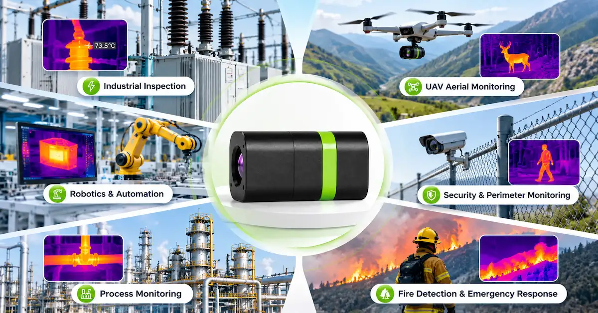

Finding a professional thermal camera supplier is straightforward. Finding one whose imaging hardware fits your product architecture, operating environment, and long-term development requirements is considerably more difficult.
For OEM manufacturers, the purchasing decision rarely ends with image resolution or unit price. An industrial inspection instrument needs suitable thermal contrast and a dependable imaging interface. A UAV payload must fit strict electrical and mechanical limits. An autonomous robot needs thermal images that its onboard system can acquire, process, and use.
A professional supplier should help buyers connect these requirements to an appropriate thermal imaging core, optical configuration, and integration strategy. It should also explain what can be confirmed from published specifications and what requires additional engineering validation.
The most useful selection principle is to begin with the task the finished equipment must perform, then work backward to the thermal detector, optics, electronics, interfaces, and supplier responsibilities.
This guide is designed for OEM product developers, technical purchasing managers, industrial equipment manufacturers, UAV integrators, and professional infrared equipment distributors. It explains how to translate operating requirements into an effective purchasing specification, compares EAGLET's published uncooled thermal imaging cores, and identifies the information buyers should obtain before committing to an integration project.
1. What Makes a Professional Thermal Camera Supplier Different?
A professional thermal camera supplier is not defined solely by the number of camera models in its catalog.
For equipment manufacturers, a useful supplier must offer products that can satisfy a defined imaging task and provide enough technical information to support purchasing and integration decisions.
There is also an important distinction between a supplier of complete thermal cameras and a supplier of embedded thermal imaging components.
A finished thermal camera might include a display, battery, user interface, data storage, wireless communications, or calibrated temperature measurement functions.
A thermal imaging core is generally intended to become part of another product. It supplies the infrared imaging capability while leaving some system-level functions to the equipment manufacturer.
Understanding different supplier models
| Supplier type | Typical product scope | Most suitable customers |
|---|---|---|
| Finished thermal camera supplier | Complete inspection or observation equipment | Industrial end users, maintenance teams, professional distributors |
| Thermal imaging core supplier | Detector-based imaging modules with optics and processing electronics | OEM manufacturers, equipment developers, embedded system designers |
| Infrared system integration partner | Thermal modules combined with customer-specific hardware and system functions | Robotics companies, UAV manufacturers, industrial system integrators |
| Specialized optical solution provider | Application-specific optical and imaging subsystems | Developers with unusual optical or mechanical requirements |
A supplier may operate in more than one category.
EAGLET's publicly described business focuses on thermal imaging cores and intelligent vision solutions, with OEM/ODM integration support for equipment manufacturers and system integrators.
This distinction matters when a buyer searches for a professional thermal camera supplier.
A distributor seeking finished handheld inspection cameras may have different requirements from an engineering company developing a proprietary thermal monitoring device.
Before comparing suppliers, identify whether you need a finished product, an integration-ready thermal core, or a custom imaging subsystem.
Choosing the wrong supplier category can create unnecessary engineering work, incomplete quotations, and unrealistic expectations about product functionality.
2. Start With the Application, Not the Thermal Camera Specifications
A common sourcing mistake is selecting a detector resolution before defining what the camera must observe.
A resolution of 640×512 may appear more desirable than 256×192, but the higher pixel count is only valuable when it addresses an actual application requirement.
A professional thermal camera supplier should be able to discuss the relationship between the imaging task and the required optical, electrical, and mechanical configuration.
Five questions that should come before product selection
What must the equipment observe?
Determine whether the target is an electrical connection, a machine component, a person, an animal, a vehicle, or a broader temperature pattern.
At what distance will the camera operate?
The same object occupies a smaller proportion of the thermal image as observation distance increases, assuming a fixed optical configuration.
Does the application require observation or measurement?
Detecting an abnormal thermal pattern is not the same as reporting an accurately calibrated temperature.
How will the thermal image enter the existing system?
A module's video output and control interface must match the host electronics or an approved acquisition path.
What are the physical and environmental limitations?
Installation space, available power, mechanical loading, operating temperature, and enclosure conditions may eliminate otherwise attractive products.
Application-driven selection matrix
| Application | Primary requirement | Technical priority | Important purchasing question |
|---|---|---|---|
| Industrial inspection equipment | Detect relevant thermal anomalies | Optical coverage, image quality, integration | Will the target occupy enough pixels at the working distance? |
| EV charging monitoring | Observe components subject to abnormal heating | Thermal observation or validated radiometry | Does the application need visual anomalies or calibrated temperature readings? |
| UAV inspection payload | Obtain useful imagery within payload limits | Weight, size, power, video path | Can the module fit and communicate with the flight payload electronics? |
| Inspection robotics | Add thermal sensing to autonomous equipment | Embedded interfaces, power, latency | Can the robot's processor capture and use the video? |
| Professional security systems | Observe targets in low-visible-light conditions | FOV, thermal contrast, operating environment | What detection performance is required for the target and location? |
| Compact portable equipment | Integrate thermal imaging in limited space | Mechanical configuration, power, optics | Can the module operate within the enclosure and power budget? |
These requirements are different enough that a single thermal camera model should not automatically be recommended for every application.
For procurement teams, the application matrix is a useful first filter. It prevents supplier comparisons from becoming a competition between isolated specifications.
3. Select the Correct Thermal Imaging Technology
Professional infrared imaging systems can use different detector technologies and spectral bands.
For the uncooled thermal cores publicly listed by EAGLET, the relevant technology is long-wave infrared imaging based on vanadium oxide detectors.
3.1 Uncooled VOx infrared detectors
VOx stands for vanadium oxide. In an uncooled microbolometer, incident infrared radiation changes the temperature of sensing elements, producing a measurable electrical response.
The imaging electronics process these responses to produce a thermal image.
Uncooled detectors do not require the cryogenic cooling systems associated with certain high-performance cooled infrared detector technologies.
This can make uncooled modules attractive for compact industrial equipment, portable systems, and embedded imaging platforms.
However, the absence of cryogenic cooling does not mean that thermal management becomes unnecessary.
Electronic components, image processing hardware, ambient temperature, and enclosure design can still influence system operation.
3.2 Long-wave infrared spectral response
EAGLET's published thermal imaging core specifications describe a spectral response of 8–14 μm.
This is within the long-wave infrared region commonly used in thermal imaging applications.
LWIR imaging can provide useful thermal contrast without visible illumination, making it relevant to inspection and nighttime observation.
Nevertheless, material transmission and environmental effects remain important.
For example, ordinary visible-light window glass is generally not transparent to the LWIR wavelengths used by these modules. A thermal camera positioned behind ordinary glass may therefore observe the glass rather than the intended scene beyond it.
Buyers should not interpret infrared imaging as an unrestricted ability to see through every obstacle.
3.3 Detector pixel pitch
The EAGLET thermal cores discussed in this article publicly specify a 12 μm detector pixel pitch.
Pixel pitch describes the spacing between detector elements.
It influences the detector's physical dimensions and its relationship with the optical system.
A smaller pixel pitch is not automatically an indication of better performance. The lens, detector resolution, optical quality, and intended imaging task must be considered together.
For engineering procurement, the complete detector-and-optics configuration matters more than any single specification.
4. How to Compare EAGLET Thermal Imaging Cores for OEM Projects
EAGLET's published product range includes five thermal imaging core entries:
-
T-C Series Multifunctional Thermal Imaging Core
-
T256-S Compact Thermal Imaging Core Module
-
T384-I Multifunctional Thermal Imaging Core Module
-
T640-S High Performance Thermal Imaging Core Module
-
T640-I High Resolution Multifunctional Thermal Imaging Core
The T-C Series additionally provides three listed detector resolution configurations.
These products offer different starting points for professional imaging integration.
EAGLET thermal imaging core comparison
| EAGLET model | Detector resolution | Published NETD | Power consumption | Integration consideration |
|---|---|---|---|---|
| T-C Series | 256×192 / 384×288 / 640×512 | ≤35 mK | ≤0.5 W | Multiple resolution configurations, published UART control |
| T256-S | 256×192 | ≤50 mK | <1.5 W | Compact lens and controller arrangement |
| T384-I | 384×288 | ≤50 mK | <1.5 W | Integrated module configuration |
| T640-S | 640×512 | ≤50 mK | <1.5 W | Separately specified optical module and controller |
| T640-I | 640×512 | ≤50 mK | <1.5 W | Compact integrated configuration, 63 g published weight |
Values are drawn from EAGLET's public product information. NETD conditions are not uniformly documented across all product families. Buyers should confirm the exact model, optical configuration, electrical version, and current datasheet before purchase.
The listed models use uncooled VOx detectors and specify CVBS (PAL) video output.
Published frame rates are 50 fps or 50 Hz for the T256-S, T384-I, T640-S, and T640-I; the T-C Series lists 50/60 Hz configurations.
Frame rate and external video format are separate technical considerations, which should be verified during integration.
4.1 T-C Series: Multiple resolution options and low published power consumption
The EAGLET T-C Series includes T-C2, T-C3, and T-C6 configurations.
The series publicly specifies low power consumption of no more than 0.5 W, a 4.5–18 V power input, and UART control.
This creates an interesting option for equipment designers facing limited electrical power or installation space.
Potential evaluation scenarios include battery-powered inspection instruments, embedded industrial devices, and mobile imaging platforms.
However, purchasers should confirm that the published physical and electrical specifications apply to the exact detector resolution and optical configuration being considered.
4.2 T256-S: Compact imaging for space-constrained projects
The T256-S Compact Thermal Imaging Core uses a 256×192 detector.
Its published specifications include a 50 fps frame rate, 9–24 V input, less than 1.5 W power consumption, and separately listed dimensions for the lens assembly and main control electronics.
This architecture may appeal to developers who need flexibility in component placement.
A 256×192 detector should not be rejected simply because higher resolutions are available. For suitable target sizes and observation distances, it may provide enough imaging information for the task.
The practical decision should come from optical coverage and sample testing.
4.3 T384-I: An intermediate-resolution integrated option
The T384-I Multifunctional Thermal Imaging Core provides 384×288 detector resolution.
Its published mechanical dimensions are 35×26×49 mm, with a listed weight of 74 g.
For an OEM project where 256×192 offers insufficient target detail but a 640×512 detector is not required, this configuration may deserve evaluation.
It could be considered for fixed industrial monitoring equipment, professional inspection devices, and robotics applications.
The suitability of any particular installation must still be established using the correct optical information and application requirements.
4.4 T640-S: High resolution with a separated mechanical arrangement
The T640-S High Performance Thermal Imaging Core uses a 640×512 VOx detector.
Its public specifications list a 50 fps frame rate and separate dimensions for the lens module and main controller.
This distinction matters to product developers with restrictions on where optics and processing electronics can be placed.
For example, a custom imaging payload may have a narrow optical opening but additional space elsewhere for electronics.
A separated arrangement can be worth investigating in such situations, subject to the actual approved mounting, connector, and cable design.
4.5 T640-I: Compact, integrated high-resolution imaging
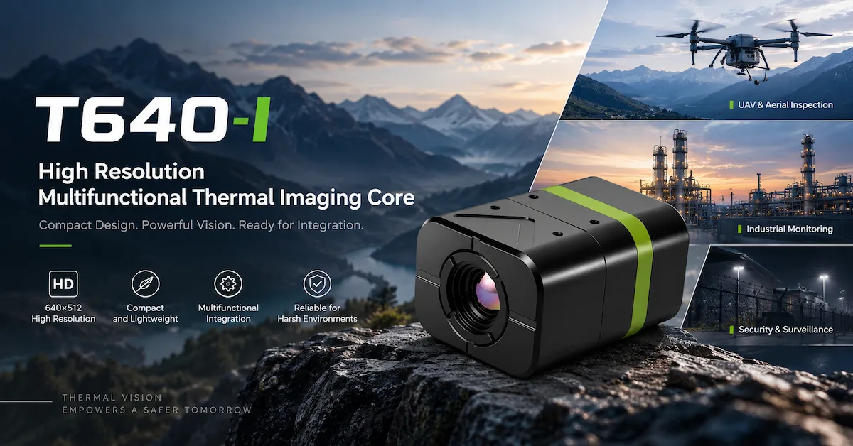
The T640-I High Resolution Multifunctional Thermal Imaging Core also provides 640×512 resolution.
Its published specifications include a 35×26×44 mm integrated form factor, 63 g weight, 9–24 V input, and power consumption below 1.5 W.
For buyers seeking a compact integrated configuration, it offers a different mechanical starting point from the T640-S.
The choice between these two cores should depend on the available installation geometry and the confirmed optical and electronic configuration, rather than assuming one is universally better.
Need to compare configurations for your product? View EAGLET's thermal imaging core range, then discuss your OEM requirements with EAGLET.
5. How Much Thermal Camera Resolution Does Your Application Really Need?
Detector resolution is one of the easiest specifications to compare, but it is also one of the most frequently overemphasized.
Consider three common formats.
| Detector resolution | Total pixels | Relative horizontal pixel count |
|---|---|---|
| 256×192 | 49,152 | 1.0× |
| 384×288 | 110,592 | 1.5× |
| 640×512 | 327,680 | 2.5× |
At the same horizontal field of view, a 640-pixel-wide detector samples the scene at 2.5 times the horizontal pixel count of a 256-pixel-wide detector.
That can provide more potential image detail, but it does not automatically translate into a specific increase in detection range.
Start with target pixel coverage
Assume two camera systems observe the same target from the same distance and use optics providing the same horizontal field of view.
If the target occupies 10 horizontal pixels in a 256×192 image, it would occupy approximately 25 pixels in a 640×512 image under the same simplified geometry.
This may help with examining target shape or localized thermal patterns.
However, image quality also depends on focus, contrast, motion, noise, optical transmission, processing, and environmental conditions.
More pixels cannot compensate for every weakness elsewhere in the imaging chain.
Distinguish detection, recognition, and identification
These terms describe different levels of information.
Detection means recognizing that a relevant object or thermal feature is present.
Recognition generally means distinguishing an object's category or type.
Identification requires a higher degree of detail to determine specific identifying characteristics.
There is no universal observation distance for each level based only on detector resolution.
A professional thermal camera supplier should request the target dimensions, viewing conditions, distance, and required decision before estimating suitable optics.
When higher resolution may not be necessary
A fixed industrial system that only needs to observe a large component from a short distance may not benefit enough from a higher-resolution detector to justify the associated system choices.
Conversely, a platform observing smaller targets across a wider area may require more pixels.
The correct purchasing question is not simply:
Which camera has the most pixels?
It is:
Which detector and optical configuration provides sufficient usable information for the task under the intended operating conditions?
6. NETD and Temperature Accuracy: A Critical Buying Distinction
Many professional thermal camera suppliers emphasize thermal sensitivity.
A frequently used specification is NETD, short for Noise Equivalent Temperature Difference.
NETD characterizes thermal sensitivity under defined measurement conditions.
A smaller published NETD value generally indicates the ability to distinguish smaller temperature differences from image noise when other testing conditions are comparable.
However, NETD should not be confused with absolute temperature measurement accuracy.
An example from industrial monitoring
Imagine a machine inspection system that displays one component as brighter than neighboring components.
The contrast may indicate a temperature difference worth investigating.
But if the system is required to trigger an alarm at a calibrated component temperature, additional technical questions arise.
Does the camera support radiometric measurement?
What temperature range is covered?
How are emissivity and reflected radiation handled?
What calibration and measurement uncertainty apply?
Does the system provide usable numerical temperature data to the customer's software?
A thermal imaging core that generates an excellent image does not automatically satisfy these requirements.
Questions to ask about thermal sensitivity
When comparing NETD claims, buyers should establish the measurement conditions, optical configuration, relevant operating temperature, and whether the stated value represents the exact quoted model.
The T-C Series currently publishes a NETD value of ≤35 mK, while the other four listed EAGLET cores publish ≤50 mK under their stated product conditions.
These figures should not be treated as a controlled performance ranking unless the measurement methods and configurations are comparable.
If your application requires calibrated temperature measurement, specify that function explicitly in the RFQ. Do not assume it is included in a standard imaging module.
7. Video Interfaces Can Determine Whether an OEM Project Succeeds
A thermal imaging core may meet the required detector resolution and still be unsuitable for the customer's electronics.
One critical consideration is the external video signal.
7.1 Understand CVBS (PAL) output
EAGLET's published thermal imaging core specifications list CVBS (PAL) video output.
CVBS is an analog composite video interface.
It is different from native digital interfaces such as USB, MIPI CSI-2, or Ethernet.
For an OEM device built around a digital processor, this difference can affect system architecture.
An additional video capture or conversion stage may be necessary.
Buyers should verify the actual delivered signal and host compatibility instead of assuming that the sensor resolution is available as raw digital image data.
7.2 Establish control-interface requirements
A thermal imaging product may need remote control of image functions or configuration settings.
The T-C Series publicly lists UART control.
That does not establish that every EAGLET module offers the same command set, connector arrangement, or firmware functionality.
Before integration, the engineering team should request the relevant interface documents for the exact hardware revision.
Questions worth resolving include whether control commands are required, how the host initializes the module, and how the final system manages startup or fault conditions.
7.3 Frame rate is not the same as end-to-end latency
An imaging core's frame rate describes image acquisition or generation frequency under the specified operating mode.
End-to-end system latency includes everything that happens after the original image is captured.
A typical chain may contain:
Thermal detector → Image processing → Video output → Host capture → Transmission → Display or software processing
Each stage can introduce delay.
For a stationary inspection device, additional delay may be acceptable.
For a remotely operated UAV or moving robot, latency may be more significant.
Some EAGLET thermal core specifications publish imaging latency below 20 ms. This should not be interpreted as a guarantee for the complete equipment or transmission system.
The final latency requirement must be validated at the system level.
8. Professional Thermal Cameras for Industrial Inspection and EV Equipment
Industrial thermal imaging applications often require reliable observation under repeatable operating conditions.
The equipment may be used in manufacturing plants, electrical installations, inspection stations, or automated monitoring systems.
For a manufacturer developing such equipment, the first task is to define what the thermal image contributes to the inspection process.
Electrical and mechanical inspection
Thermal imaging can support non-contact observation of thermal patterns associated with electrical connections, mechanical components, and operating equipment.
Potential tasks include identifying differences between similar components, observing unexpected heating, or documenting thermal changes during operation.
However, the image should be interpreted within the relevant electrical and mechanical context.
A warm component is not necessarily defective. Load conditions, surrounding temperatures, materials, and expected operating characteristics all matter.
Integrating thermal vision into a fixed inspection station
A fixed inspection station has different requirements from a portable maintenance camera.
The station may have a known working distance and repeatable target position.
This allows the designer to establish a consistent optical arrangement, but it also makes correct lens selection important.
The camera should capture the required region of interest with sufficient detail.
Other engineering considerations include mechanical alignment, shielding from unwanted radiation, host processing, and environmental temperature changes.
EAGLET describes related application directions in its industrial inspection solutions.
EV charging and power electronics
Thermal vision may also support inspection of charging-related electrical equipment.
Connectors, power conversion devices, and distribution components can experience localized heating under particular operating conditions.
If the intended function is qualitative thermal observation, image-based assessment may provide useful information.
If the requirement is a calibrated alarm at a defined temperature threshold, the customer must verify radiometric capabilities and the complete alarm logic.
For outdoor charging equipment, the system designer should also assess environmental exposure and enclosure protection.
Review EAGLET's new-energy and EV charging application direction when defining the imaging requirements.
9. How UAV Manufacturers Should Evaluate a Thermal Imaging Supplier
UAV imaging projects are an example of why a supplier's integration capabilities can matter more than its standard product catalog.
A drone camera module operates within a restricted payload envelope and depends on the surrounding airborne system.
Weight and mechanical arrangement
Payload designers should consider total installed mass rather than the imaging core's published weight alone.
Mounting hardware, cables, enclosure components, protective structures, and other equipment contribute to the final payload.
The mechanical arrangement of the imaging module can also affect the overall layout.
EAGLET's T640-S and T640-I offer different published physical configurations, making their mechanical suitability an important selection consideration.
Electrical power and operating time
A thermal imaging core consumes power from the host system.
The designer must consider supply voltage, steady-state consumption, startup behavior, and the complete power architecture.
A module with lower published electrical consumption may be advantageous in some systems, but it must still provide the necessary imaging performance and interface compatibility.
Optical requirements in aerial inspection
Observation distance can vary with flight altitude, viewing angle, and target position.
A camera selected without considering those factors may provide insufficient target detail even when its detector resolution appears adequate.
Buyers should define representative observation geometry and request suitable optical data.
Video transmission and display
The camera's output must be compatible with the payload processing and transmission system.
If the module provides CVBS while the transmission hardware expects another input format, the architecture must account for that difference.
The complete video path should be tested using the actual intended hardware.
EAGLET provides additional application context through its UAV and low-altitude vision solutions.
For UAV OEM buyers, the most useful supplier is one that can discuss the thermal core and its surrounding system requirements as separate but connected engineering problems.
10. Thermal Imaging for Robotics and Embedded Systems
Robotic equipment introduces another set of purchasing considerations.
An inspection robot may combine visible-light cameras, navigation sensors, computing hardware, and thermal imaging in a relatively small enclosure.
The infrared module must fit this environment without compromising the rest of the system.
Electrical integration
The thermal core must operate within the robot's available electrical supply.
Power consumption is important, but voltage compatibility, power sequencing, electrical noise, and connector arrangement may be equally significant.
A system can fail to operate correctly even when its total power budget appears sufficient.
Mechanical and thermal design
Robotic enclosures can contain motors, processors, batteries, and other heat-producing components.
Their position relative to the thermal camera may affect the local operating environment or introduce unwanted thermal features.
The imaging system may therefore require careful component placement, suitable enclosure design, and application-specific testing.
Image acquisition and processing
The robot's onboard processor must be able to receive and interpret the video signal.
If the system uses digital computer vision software, engineers should verify the acquisition path before selecting a core.
Thermal imagery alone does not automatically provide object tracking, recognition, navigation, or automated fault diagnosis.
These functions may require additional software, processing resources, sensors, and validation.
Continuous operation
An embedded thermal imaging system may run for extended periods without an operator manually checking the image.
Long-duration testing should therefore evaluate startup behavior, video stability, environmental performance, and recovery from relevant fault conditions.
For these applications, technical integration support and accurate documentation are key supplier-selection factors.
11. Which Operating Environments Need Additional Verification?
A professional thermal camera supplier should be able to distinguish the operating conditions of a module from the requirements of the completed product.
This matters particularly when the camera is integrated into equipment exposed to dust, moisture, vibration, or significant temperature changes.
Operating temperature
EAGLET's publicly listed T-C Series specifies a working temperature range of -40°C to +60°C.
The T256-S, T384-I, T640-S, and T640-I publish ranges of -20°C to +60°C.
These are model-level published specifications, not guarantees that every integrated system will operate correctly at those temperatures.
The finished enclosure, power electronics, mounting structure, and local heat sources may alter the actual conditions experienced by the imaging module.
Dust and water exposure
An operating temperature specification does not establish a dustproof or waterproof rating.
For outdoor equipment, the supplier and equipment manufacturer should determine whether a suitable protective enclosure is necessary.
Any claimed IP rating should be supported by evidence for the relevant product or enclosure configuration.
Vibration and mechanical loading
Mobile robots, UAVs, and industrial machinery can expose installed electronics to vibration or mechanical loading.
A thermal imaging module that works well on a laboratory bench may require additional validation once installed in a moving platform.
Buyers should establish the intended mounting conditions and appropriate test expectations.
Long-term outdoor observation
Outdoor image quality can be affected by atmospheric transmission, weather, target contrast, surface characteristics, and environmental temperature.
Thermal imaging works without visible illumination, but it does not guarantee identical imaging performance in every atmospheric condition.
For professional observation projects, representative field testing remains important.
12. A Practical Supplier Fit Matrix for OEM Purchasing Teams
Instead of ranking suppliers by price or brochure length, a useful approach is to evaluate their ability to satisfy the customer's actual equipment requirements.
The following decision matrix is intended for OEM teams comparing thermal imaging proposals.
| Evaluation category | Questions to resolve | Decision significance |
|---|---|---|
| Application compatibility | Does the proposed imaging configuration serve the actual task? | Essential |
| Optical suitability | Will the target occupy sufficient image area? | Essential |
| Electrical compatibility | Do voltage, power and startup requirements match? | Essential |
| Interface suitability | Can the host receive the necessary video and control signals? | Essential |
| Mechanical integration | Will the hardware fit and remain properly mounted? | Essential |
| Performance documentation | Are the specifications tied to the offered configuration? | High |
| Engineering support | Can the supplier clarify integration and configuration questions? | High |
| Commercial suitability | Are cost, availability and project conditions acceptable? | High |
| Long-term continuity | Can the buyer manage revisions, replacements and future orders? | High |
A supplier should not be selected merely because it performs well in less critical areas.
For example, attractive commercial terms do not compensate for a video interface that the customer's system cannot support.
Use three decision gates
Gate 1: Technical feasibility
Confirm that the proposed core can meet the imaging, optical, electrical, and mechanical requirements.
Any unresolved mandatory requirement should prevent immediate approval.
Gate 2: Integration feasibility
Confirm that the module can operate within the intended host architecture.
This includes signal acquisition, startup behavior, physical installation, and any required control functions.
Gate 3: Commercial readiness
Only after the first two gates should the buyer finalize quantities, lead times, customization responsibilities, testing agreements, and commercial terms.
This sequence reduces the risk of selecting a supplier on price before discovering expensive technical incompatibilities.
For a separate discussion of factory auditing and production evidence, see EAGLET's existing infrared thermal camera factory audit guide.
13. What Documentation Should a Professional Thermal Camera Supplier Provide?
Documentation is especially important for equipment manufacturers because the thermal imaging module becomes part of a larger engineered system.
A short product brochure is rarely sufficient for detailed integration.
Depending on the project, buyers may need:
| Technical document | Intended use |
|---|---|
| Model-specific datasheet | Confirm detector, optics, power and operating limits |
| Mechanical drawing | Design mounting, enclosure and component clearances |
| Electrical interface information | Connect supply and signal paths correctly |
| Connector and pin definitions | Prevent wiring or interface errors |
| Control protocol information | Implement supported external commands |
| Optical configuration details | Confirm FOV and application suitability |
| Hardware and firmware identification | Control the approved configuration |
| Application-specific test information | Verify required performance |
| Commercial and support terms | Plan purchasing, maintenance and future production |
Not every item will be publicly downloadable, and availability depends on the product and project.
EAGLET's technical support page asks buyers to identify the exact model, intended application, language, and relevant revision when requesting technical documents.
This is a useful practice for any OEM purchasing team.
A module should not be approved using an unspecified or outdated document when the intended design depends on precise dimensions, electrical connections, or optical specifications.
14. From Engineering Sample to Production-Ready Imaging System
Selecting a promising thermal imaging core is only the first stage of a successful equipment development project.
The integration should be validated using a repeatable process.
Stage 1: Confirm the application requirements
Document the intended observation task, target size, working distance, environmental conditions, and system architecture.
Separate mandatory requirements from desirable features.
For example, a fixed control-board connector may be mandatory, while detector resolution might remain open to evaluation.
Stage 2: Obtain the correct sample configuration
Request a sample identified by its exact model and approved configuration.
Confirm what optical components and interfaces are included.
Do not assume a demonstration sample is identical to the configuration proposed for volume purchasing.
Stage 3: Perform bench integration
Connect the thermal module to the intended power supply and host electronics.
Verify video acquisition, applicable controls, power behavior, and startup operation.
Document the results rather than relying on visual impressions.
Stage 4: Evaluate representative thermal scenes
Test the module against actual or representative targets.
Record relevant conditions such as target distance, ambient environment, operating settings, and optical arrangement.
Determine whether the imaging task can be completed consistently.
Stage 5: Test within the final equipment
Install the imaging module in the representative enclosure or platform.
Recheck performance, mechanical stability, power behavior, and operating conditions.
A module can behave differently when installed near other heat sources or connected through the complete signal chain.
Stage 6: Establish production acceptance requirements
Before volume purchasing, agree on the approved configuration and the evidence necessary to confirm that delivered units meet project requirements.
This framework is a recommended OEM validation sequence, not a statement that EAGLET offers a fixed six-stage service package with predetermined acceptance terms.
The actual development workflow should be agreed between the parties.
15. Understanding the Total Cost of an OEM Thermal Imaging Solution
Professional thermal camera procurement should account for more than the quoted module price.
The total project cost may include optical design, interface hardware, embedded software, mechanical integration, sample evaluation, testing, and future maintenance.
Consider two hypothetical sourcing choices.
Option A: A less expensive core requires additional interface conversion hardware and substantial integration work.
Option B: A more expensive core fits the approved system architecture and requires fewer changes.
The lower component quotation may not represent the lower total project cost.
That outcome depends on engineering effort, purchasing volume, the existing platform, and the project schedule.
A more useful cost comparison
Buyers should evaluate:
-
Imaging core and optical configuration
-
Additional host or interface hardware
-
Engineering development and firmware changes
-
Mechanical design and installation requirements
-
Sample and prototype testing
-
Customization or one-time engineering charges
-
Production quality and documentation requirements
-
Logistics and market-specific compliance responsibilities
-
Replacement, maintenance, and future configuration management
No single thermal core configuration is always the most economical.
A small industrial device and a sophisticated UAV imaging payload may have very different cost structures.
A good supplier discussion should therefore establish the required deliverables before comparing final quotations.
16. Why EAGLET Is Relevant to Professional OEM Thermal Imaging Procurement
EAGLET positions itself as a provider of infrared thermal imaging cores and intelligent vision solutions.
According to its company profile, its business directions include infrared sensing, image processing, embedded hardware, image transmission, multispectral observation, and application-focused integration.
For OEM equipment manufacturers, this positioning is relevant because a thermal imaging component must operate within a larger engineering architecture.
A defined range of embedded thermal cores
EAGLET publishes identifiable product models across 256×192, 384×288, and 640×512 detector configurations.
The models provide different starting points for evaluating electrical consumption, mechanical layout, and integration requirements.
Technical product information for initial evaluation
Publicly listed details include detector type, spectral response, detector resolution, power requirements, operating temperature, and video output.
This information helps engineering teams begin preliminary selection before requesting detailed documents.
The published specification should still be verified against the current model configuration before design approval.
OEM/ODM integration discussions
EAGLET describes support for customer requirements involving resolution, optical selection, interfaces, mechanical integration, and software-related functions.
These capabilities are relevant to equipment manufacturers developing differentiated products.
Specific customization feasibility, engineering deliverables, and commercial conditions must be confirmed for each project.
Multiple professional application directions
EAGLET identifies industrial inspection, new-energy equipment, security observation, UAV systems, search and rescue, and outdoor monitoring among its application directions.
These areas help prospective customers frame an appropriate technical inquiry.
They should not be interpreted as evidence that every listed imaging core has already been validated for every possible deployment.
If your project involves an OEM thermal imaging module rather than a standard finished consumer camera, explore EAGLET products and request an application-specific technical discussion.
17. A Technical RFQ Template for Professional Thermal Camera Buyers
A professional supplier can usually respond more effectively when the buyer provides a clear technical brief.
A request containing only the required pixel resolution may lead to assumptions about the intended optics, interfaces, or product scope.
Use the following RFQ structure for your project.
| RFQ requirement | Information to provide |
|---|---|
| Company and project | OEM company, equipment type, development stage |
| Intended application | Inspection, monitoring, UAV, robotics or another use |
| Thermal imaging objective | Detection, observation, recognition or calibrated measurement |
| Target | Object type, approximate size and relevant thermal conditions |
| Working distance | Typical and maximum intended distances |
| Required field of view | Desired scene coverage or installation geometry |
| Detector resolution | Required or preferred resolution |
| Host architecture | Existing controller, processor and receiving interface |
| Video output | Required format and acquisition constraints |
| Control functions | Required command or integration behavior |
| Electrical supply | Available voltage and operating power budget |
| Mechanical limitations | Maximum size, weight and mounting conditions |
| Environmental conditions | Operating temperature, enclosure exposure and mechanical conditions |
| Prototype plan | Expected sample quantity and evaluation stage |
| Purchasing requirements | Indicative production quantities, schedule and destination |
This information does not need to be perfectly complete before contacting a supplier.
However, identifying the unknowns makes the engineering discussion more productive.
Example RFQ: Industrial inspection equipment
An industrial equipment developer might provide the following:
We are developing a fixed thermal inspection module for monitoring components inside industrial machinery. The imaging system must observe specific target regions from a defined working distance and integrate with our existing electronics. We would like to compare detector resolution options and understand the available CVBS interface, optics, mechanical drawings, and power requirements. Please recommend an appropriate module configuration and confirm the technical documents available for evaluation.
Example RFQ: UAV thermal imaging payload
A UAV developer might write:
We are designing a compact thermal observation payload and require an infrared core compatible with our power supply and video system. Our priorities are installed mass, optical field of view, mechanical dimensions, and image latency through the intended video chain. We are considering 384×288 and 640×512 configurations. Please advise which published modules are appropriate for technical evaluation.
These are illustrative inquiries rather than actual customer projects.
Both provide significantly more useful information than a generic request for a catalog and price list.
Buyers can submit their project information through the EAGLET contact page.
18. Frequently Asked Questions About Professional Thermal Camera Suppliers
What should OEM buyers prioritize when choosing a professional thermal camera supplier?
OEM buyers should prioritize compatibility with the intended equipment, suitable imaging performance, reliable documentation, and the ability to clarify technical requirements.
Resolution, optical field of view, power consumption, video interface, mechanical configuration, and operating environment should be evaluated together.
Supplier pricing and commercial terms remain important, but they cannot compensate for a module that does not meet mandatory technical requirements.
Is an infrared thermal imaging core the same as a complete professional thermal camera?
No. A thermal imaging core provides the fundamental infrared imaging function for integration into another device.
A complete camera may include additional hardware and software such as a display, storage, enclosure, user controls, communications, and calibrated measurement functions.
Buyers should confirm the product scope before comparing quotations.
Is 640×512 always better than 384×288 for industrial inspection?
Not necessarily.
A 640×512 detector offers more pixels, but the practical benefit depends on target size, observation distance, optical field of view, and the imaging task.
For large nearby targets, a lower-resolution module may be sufficient.
For applications requiring more potential spatial detail, 640×512 may be worth evaluating.
The decision should be validated with the intended optics and application conditions.
Can EAGLET thermal imaging cores connect directly to USB or MIPI processors?
The EAGLET thermal core models discussed here publicly list CVBS (PAL) video output.
That is an analog composite video format, not a native USB or MIPI digital output.
Compatibility with a digital host may require additional acquisition hardware or a separately confirmed interface solution.
Buyers should request the exact interface documentation before integration.
Does low NETD guarantee accurate temperature measurement?
No. NETD describes thermal sensitivity under defined conditions, not absolute temperature measurement accuracy.
Accurate radiometric measurement requires additional functionality, appropriate calibration, and consideration of the measurement environment.
If numerical temperature measurement is essential, the buyer should request confirmed radiometric specifications for the exact proposed system.
Which EAGLET thermal core should a UAV manufacturer consider?
The decision depends on the target, optical coverage, payload mass, electrical limits, and video architecture.
The T256-S, T384-I, T640-S, and T640-I offer different detector resolutions and mechanical configurations.
The T-C Series also provides several resolution options and a low published power-consumption specification.
A UAV buyer should shortlist candidates using the actual payload requirements, then validate the complete system.
What information should I send when requesting a professional thermal camera quotation?
Provide the application, expected target characteristics, observation distance, required image or measurement function, preferred resolution, video interface, electrical power, size limitations, operating environment, and estimated purchasing quantity.
If a specific EAGLET model is under consideration, include its model name.
This information helps the supplier determine whether a published module or a customized integration approach should be discussed.
Conclusion
Selecting a professional thermal camera supplier begins with matching the imaging solution to the equipment's actual operating requirements.
For OEM manufacturers, industrial inspection equipment developers, UAV companies, and robotic system integrators, the most important decisions involve optical coverage, detector resolution, interface compatibility, electrical and mechanical integration, and application-specific validation.
EAGLET's published range of VOx uncooled thermal imaging cores provides several potential starting points for professional OEM development, from compact 256×192 modules to 640×512 integrated imaging configurations.
The next step is to identify the exact requirements of your product and verify which module configuration can satisfy them.
Explore EAGLET Thermal Imaging Cores to review the available models, or Contact EAGLET for an OEM Thermal Imaging Solution to discuss your application's optical, electrical, mechanical, and purchasing requirements.